

DC-DC and DC-AC power conversion system
a power conversion system and ac technology, applied in the field of power electronics, can solve the problems of reducing the power density of conventional electrical systems, affecting the efficiency of power conversion,
- Summary
- Abstract
- Description
- Claims
- Application Information
AI Technical Summary
Benefits of technology
Problems solved by technology
Method used
Image

Examples
Embodiment Construction
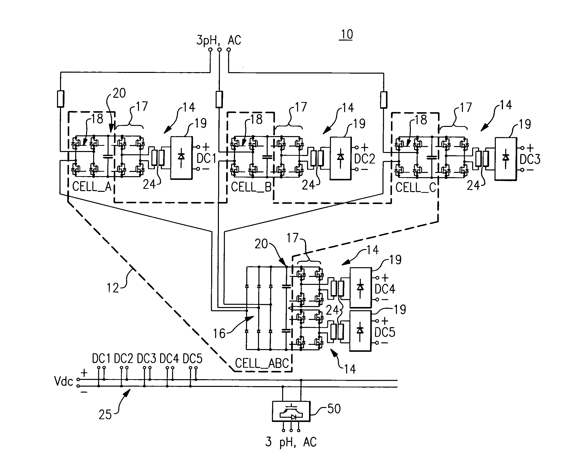
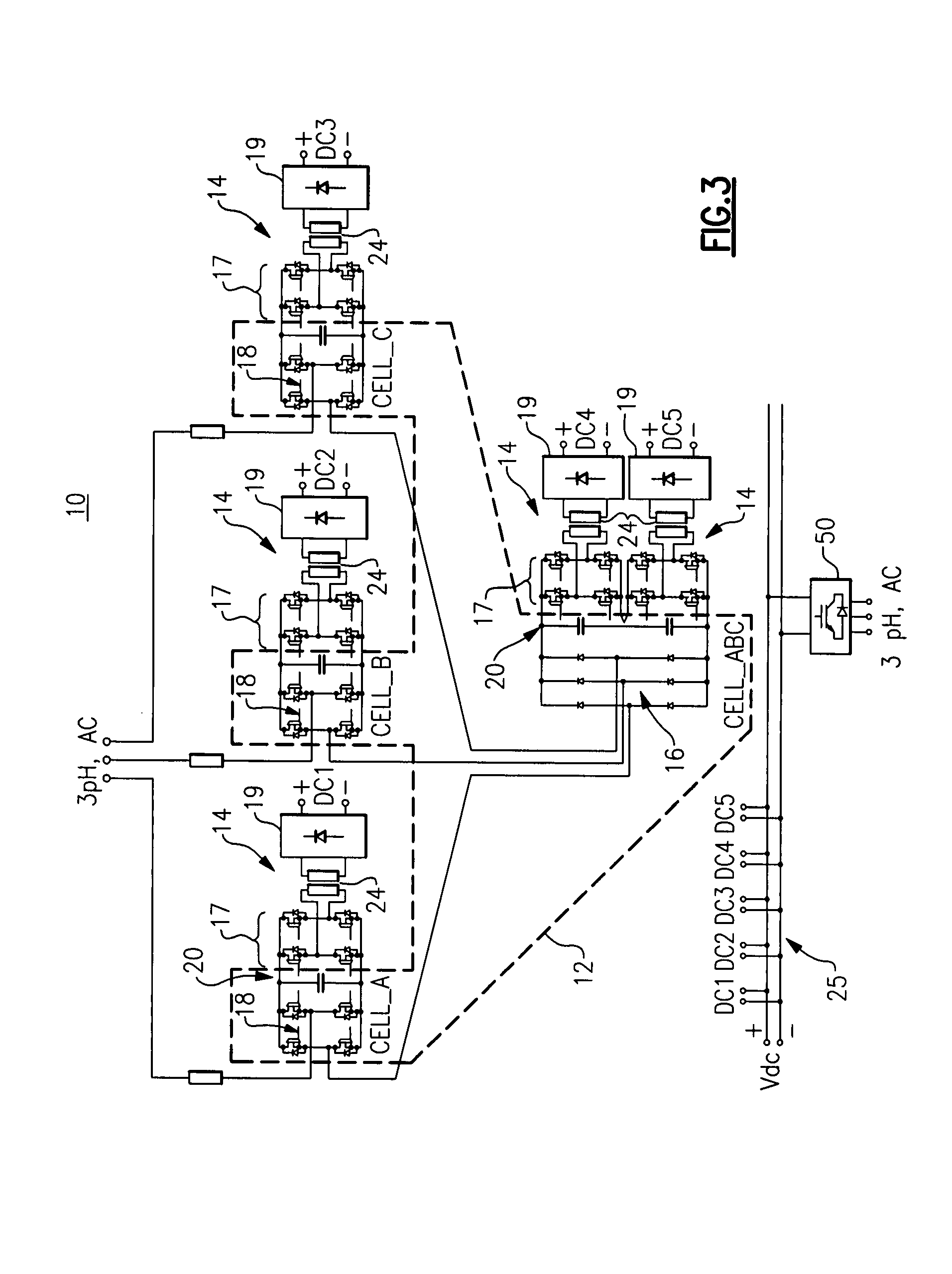
[0031]FIG. 3 illustrates a power conversion system (solid-state power substation (SSPS)) 10 that employs a plurality of modular DC-DC and DC-AC power converters, each including a high frequency galvanic isolation transformer 24, to provide a form and fit replacement for a conventional iron core transformer. The power conversion system 10 embodiment illustrated in FIG. 3 is based upon 1) rectification of high voltage AC to high voltage DC links by using a Si SCR or diode bridge 16 combined with SiC MOSFET H-bridges 18; 2) modular SiC MOSFET H-bridge DC-DC converters 14 inverting high voltage DC links to high frequency AC links; 3) modular high frequency transformers 24 coupled to the high frequency AC links; 4) rectifiers 19 at the secondary side of the high frequency transformers 24 to create a DC bus 25; and 5) output power block 50 to construct a desired AC voltage output signal.
[0032]Each DC-DC converter 14 can be seen to include a modular H-bridge DC-DC power converter with a ga...
PUM
 Abstract
Description
Claims
Application Information