Method and system for ethernet and ATM network interworking

a network interworking and ethernet technology, applied in the field of network communication, can solve the problems of insufficient data transmission, inability to consider or address the preservation of aspects of the data transport environment such as quality of service, priorityization, and inhomogeneous network technologies. achieve different levels of performance guaran

Inactive Publication Date: 2005-07-21
RPX CLEARINGHOUSE
View PDF20 Cites 56 Cited by
  • Summary
  • Abstract
  • Description
  • Claims
  • Application Information

AI Technical Summary

Benefits of technology

[0010] The invention describes an architecture and methods that enable network interworking between Ethernet and ATM networks with single or multiple QoS levels, with different levels of performance guarantees. Network interworking enables end users to communicate using different networking protocols, without performing any specific protocol interworking functions. The architecture provides flexibility in the location and functions of the internetworking function device, and describes methods for direct interworking or interworking over other network technologies.

Problems solved by technology

Network technologies are not homogeneous.
While solutions have been proposed to allow the transport of data between end points supported by disparate technologies, such solutions are typically inefficient and inadequate solutions such as encapsulation and data extraction and simple repacketizing.
These solutions fail to consider or address the preservation of aspects of the data transport environment such as quality of service, prioritization, etc.
In addition, while standards such as Request for Comment (RFC) 2684 for the pure encapsulation of Ethernet frames for transport over ATM networks exist, these standards and their implementations do not address important aspects of networking such as service and parameters mapping, QoS as well as the ability to capitalize on efficient networking opportunities such as multiplexing several Ethernet connections on an ATM virtual channel connection (VCC).

Method used


Image

  • Method and system for ethernet and ATM network interworking
  • Method and system for ethernet and ATM network interworking
  • Method and system for ethernet and ATM network interworking

Examples


Embodiment Construction

[0050] Architecture

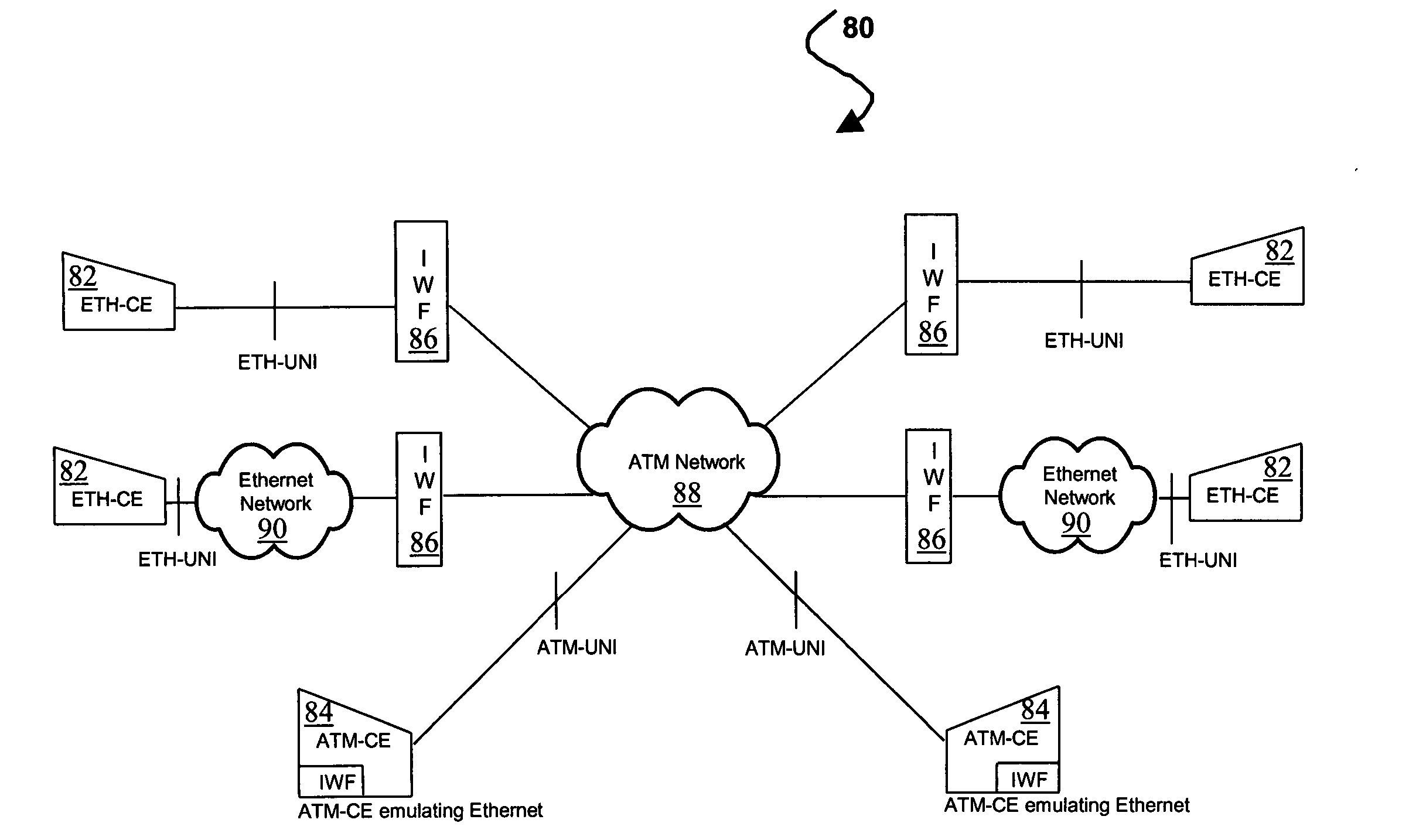
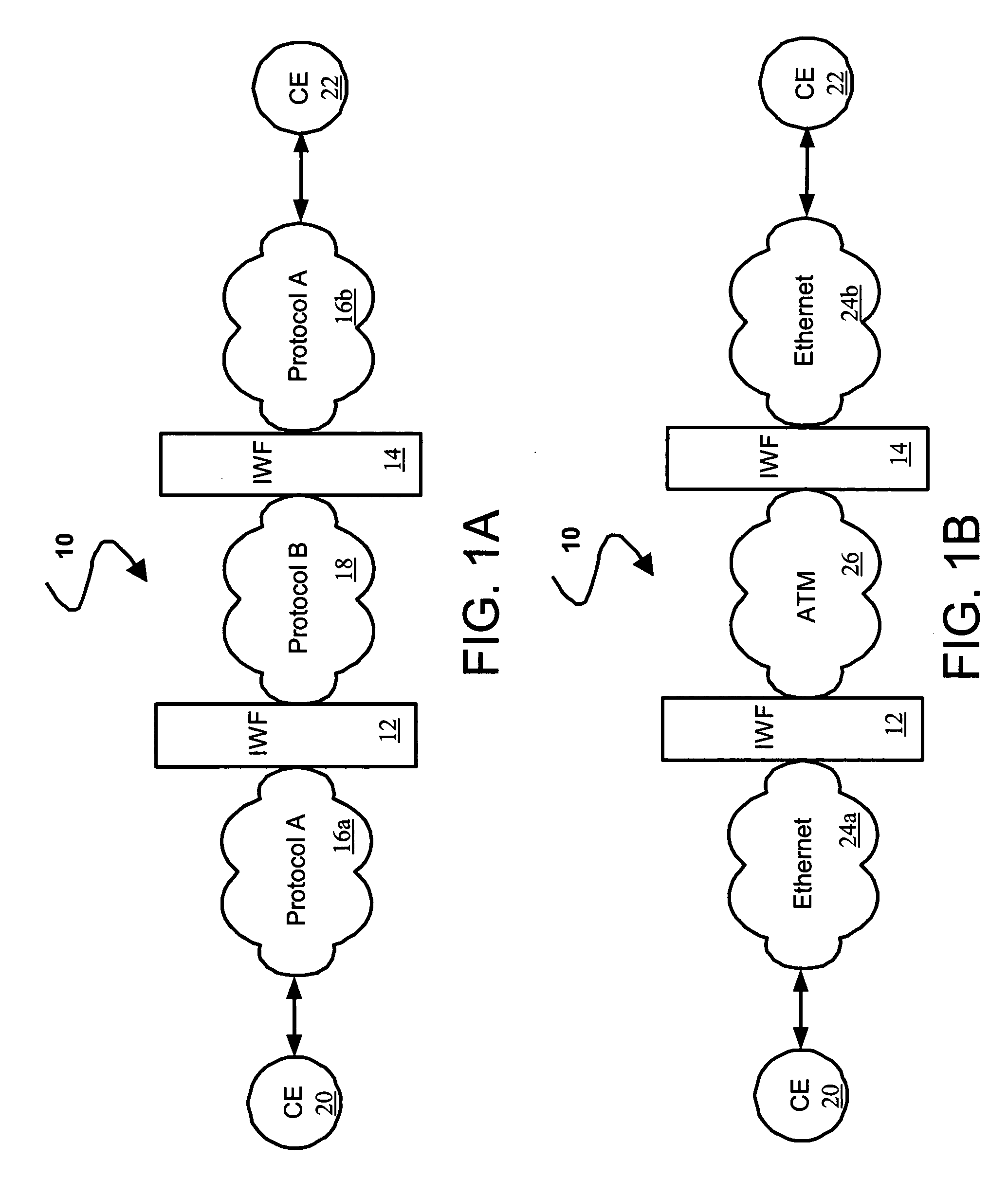
[0051] Referring now to the drawing figures in which like reference designators refer to like elements, there is shown in FIG. 1A, a system constructed in accordance with the principles of the present invention and designated generally as “10”. System 10 includes three network segments connected by interworking function (IWF) devices 12 and 14. Two segments, networks 16a and 16b are coupled to IWF devices 12 and 14, respectively, and operate using the same network protocol A. The third segment, network 18, operates using different type of network protocol from that used by networks 16a and 16b. As is shown in FIG. 1A, a communication path is formed by network 16a, IWF 12, network 18, IWF 14 and network 16b. The protocols can include, for example, Ethernet, asynchronous transfer mode (ATM), frame relay (FR), multi-protocol label switching (MPLS), and Internet protocol (IP). Customer edge (CE) devices 20 and 22, for example, routers, switches, etc. are connected to...


PUM


Abstract

A method and system for interworking between an Ethernet communication network and an ATM network, in which a first network interface is operable to communicate with the Ethernet communication network using an Ethernet communication protocol. A second network interface is operable to communicate with the ATM communication network using an ATM protocol. A processing unit is in communication with the first network interface and the second network interface, in which the processing unit encapsulates frames received from the Ethernet network into ATM frames, decapsulates frames received from the ATM network to recover Ethernet frames and maps parameters corresponding to the received one of the ATM and Ethernet frames into the other of the ATM and Ethernet frames, the mapped parameters including connection configuration control plane information and data plane parameters corresponding to individual frames.

Description

CROSS-REFERENCE TO RELATED APPLICATIONS [0001] This application is related to and claims priority to U.S. patent application No. 60 / 537,744, filed Jan. 20, 2004, entitled, ETHERNET DIFFERENTIATED SERVICES, the entirety of which is incorporated herein by reference. This application is also related to U.S. patent application Ser. No. 10 / 990,899, filed Nov. 17, 2004, entitled, METHOD AND SYSTEM FOR FRAME RELAY AND ETHERNET SERVICE INTERWORKING, and U.S. patent application No. ______, filed Dec. 9, 2004, entitled, METHOD AND SYSTEM FOR ETHERNET AND FRAME RELAY NETWORK INTERWORKING, and U.S. patent application No. ______, filed Dec. 13, 2004, entitled METHOD AND SYSTEM FOR ETHERNET AND ATM SERVICE INTERWORKING, all by the same inventors as the subject Application, the entirety of all of which are incorporated herein by reference. STATEMENT REGARDING FEDERALLY SPONSORED RESEARCH OR DEVELOPMENT [0002] n / a BACKGROUND OF THE INVENTION [0003] 1. Statement of the Technical Field [0004] The pre...

Claims


Application Information

Patent Timeline
Patent Type & Authority Applications(United States)
IPC IPC(8): H04L12/28H04L12/66H04L29/06H04L29/10
CPCH04L12/5601H04L2012/5652H04L2012/5618H04L12/66
Inventor RABIE, SAMEHMAGD, OSAMA ABOULABDULLAH, BASHARBARKA, BAGHDAD
Owner RPX CLEARINGHOUSE
Why Eureka
Try Eureka