
Hardware Migration between Dissimilar Cores

a technology of dissimilar cores and hardware, applied in the field of processors, can solve the problems of reduced supply voltage, reduced performance, and lower operating point consumption, and achieve the effect of different design/implementation and performance levels, high performance, and higher minimum voltag

Active Publication Date: 2017-03-09
APPLE INC
View PDF0 Cites 3 Cited by
  • Summary
  • Abstract
  • Description
  • Claims
  • Application Information

AI Technical Summary

Benefits of technology

The patent text describes an integrated circuit that includes processors with different designs and performance levels. Each processor state specifies an operating point, and each state is mapped to one of the processor cores. The processor can automatically switch between cores when a new state is selected, using a special purpose register interconnect. The technical effect is improved performance and efficiency in the context switch without requiring additional hardware.

Problems solved by technology

Lower operating points consume less power but also offer limited performance compared to higher operating points.
Designing a processor that can provide the performance needed by the most demanding workloads while also supporting the lowest possible operating point that would provide sufficient performance for many frequently-executed workloads has become a challenge.
Processors that operate at high operating points may only support a reduction in supply voltage to a certain level before circuitry ceases to function correctly.
Power is expended unnecessarily for such workloads, which can be a critical factor in mobile systems that frequently operate on a limited energy source such as a battery.

Method used


Image

  • Hardware Migration between Dissimilar Cores
  • Hardware Migration between Dissimilar Cores
  • Hardware Migration between Dissimilar Cores

Examples


Embodiment Construction

Processor Overview

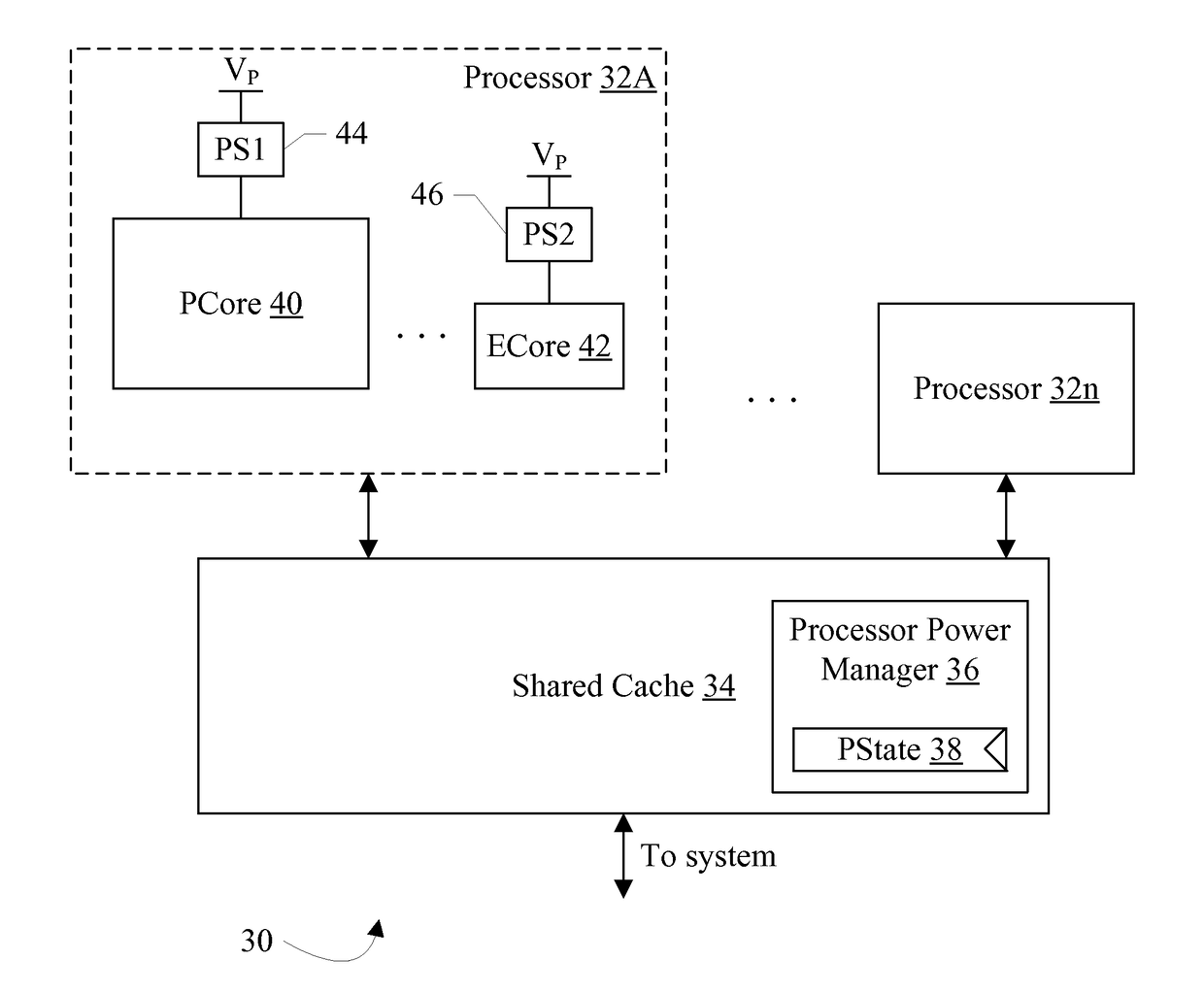
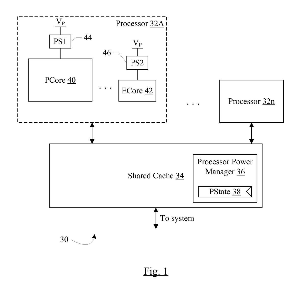
[0023]FIG. 1 is a block diagram of one embodiment of a processor cluster 30. In the illustrated embodiment, multiple processors 32A-32n and a shared cache 34 are included.

[0024]The processors 32A-32n are coupled to the shared cache 34, which is further coupled to communicate with other elements of a system that includes the cluster 30. In the illustrated embodiment, the shared cache 34 includes a processor power manager 36 that includes a PState register 38 storing a PState for the processors 32A-32n. Each processor 32A-32n may have its own independent PState, groups of processors 32A-32n may share a PState, or the cluster 30 may have a shared PState for the processors 32A-32n, in various embodiments. Processor 32A is shown in more detail in FIG. 1 to include at least two processor cores, a performance core (PCore) 40 and an efficient core (ECore) 42. Other embodiments may include additional cores. Each core 40 and 42 is coupled to a power supply rail (VP) through ...


PUM


Abstract

In an embodiment, an integrated circuit may include one or more processors. Each processor may include multiple processor cores, and each core has a different design / implementation and performance level. The processor may support multiple processor states (PStates). Each PState may specify an operating point (e.g. a combination of supply voltage magnitude and clock frequency), and each PState may be mapped to one of the processor cores. During operation, one of the cores is active: the core to which the current PState is mapped. If a new PState is selected and is mapped to a different core, the processor may automatically context switch the processor state to the newly-selected core and may begin execution on that core. The context switch may be performed using a special purpose register (SPR) interconnect. Each processor core in a given processor may be coupled to the SPR interconnect to permit access to the external SPRs.

Description

BACKGROUND[0001]Technical Field[0002]Embodiments described herein are related to processors and, more particularly, to multiple processor cores forming a processor.[0003]Description of the Related Art[0004]Various processors are included in electronic systems to execute software providing some amount of user functionality. The processors may include the central processing units (CPUs) in the system, as well as special purpose processors dedicated to specific tasks such as graphics, media processing, etc. Generally, the processors are designed to operate at multiple operating points (settings of supply voltage magnitude and clock frequency). Lower operating points consume less power but also offer limited performance compared to higher operating points. For some workloads, the limited performance is sufficient and the lower operating points can be used. For other workloads, the higher operating points are needed to provide sufficient performance.[0005]In some systems, a wide diversit...

Claims


Application Information

Patent Timeline
Patent Type & Authority Applications(United States)
IPC IPC(8): G06F9/50G06F9/30G06F9/38G06F12/08
CPCG06F9/5088G06F12/084G06F2212/314G06F9/3828G06F9/30101G06F12/0813G06F2212/1028Y02D10/00
Inventor HARDAGE, JR., JAMES N.BECKER, DANIEL U.TSAY, CHRISTOPHER M.RUSSO, RICHARD F.WEN, SHIH-CHIEH R.LARSON, RICHARD H.
Owner APPLE INC
Learn More