Heat treated profile extruded hook

Inactive Publication Date: 2003-10-02
3M INNOVATIVE PROPERTIES CO
View PDF0 Cites 35 Cited by
  • Summary
  • Abstract
  • Description
  • Claims
  • Application Information

AI Technical Summary

Benefits of technology

[0005] An alternative direct molding process is proposed, for example, in U.S. Pat. No. 4,894,060, which permits the formation of hook elements without these limitations. Instead of the hook elements being formed as a negative of a cavity on a molding surface, the basic hook cross-section is formed by a profiled extrusion die. The die simultaneously extrudes the film backing and rib structures. The individual hook elements are then formed from the ribs by cutting the ribs transversely followed by stretching the extruded strip in the direction of the ribs. The backing elongates but the cut rib sections remain substantially unchanged. This causes the individual cut sections of the ribs to separate each from the other in the direction of elongation forming discrete hook elements. Alternatively, using this same type extrusion process, sections of the rib structures can be milled out to form discrete hook elements. With this profile extrusion, the basic hook cross section or profile is only limited by the die shape and hooks can be formed that extend in two directions and have hook head portions that need not taper to allow extraction from a molding surface. This is extremely advantageous in providing higher performing and more functionably versatile hook structures. However, a limitation with this method of manufacture is in forming hook structures that are extremely narrow in the extrusion direction of the ribs or the cut direction. Cutting the formed ribs at very closely spaced intervals is difficult at commercially acceptable production speeds. Further, when the cut length is extremely closely spaced the previously cut portions of the ribs tend to fuse due to the heat created by the cutting operation. As such, there is a need to improve this process so as to allow for production of narrower hook profiles and formation of the narrower hook profiles at commercially acceptable production speeds.
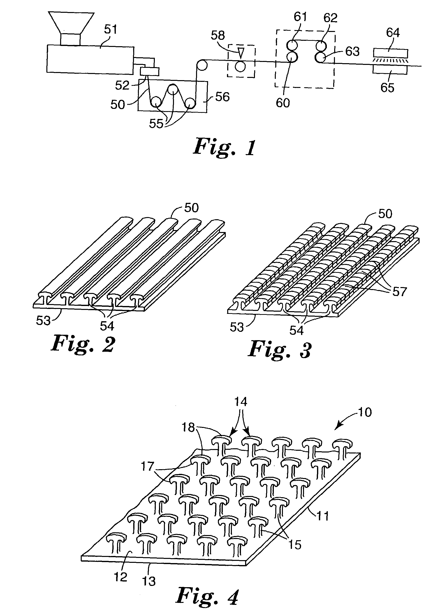
[0031] After cutting of the ribs 54, the base 53 of the strip 50 is longitudinally stretched at a stretch ratio of at least 2 to 1, and preferably at a 
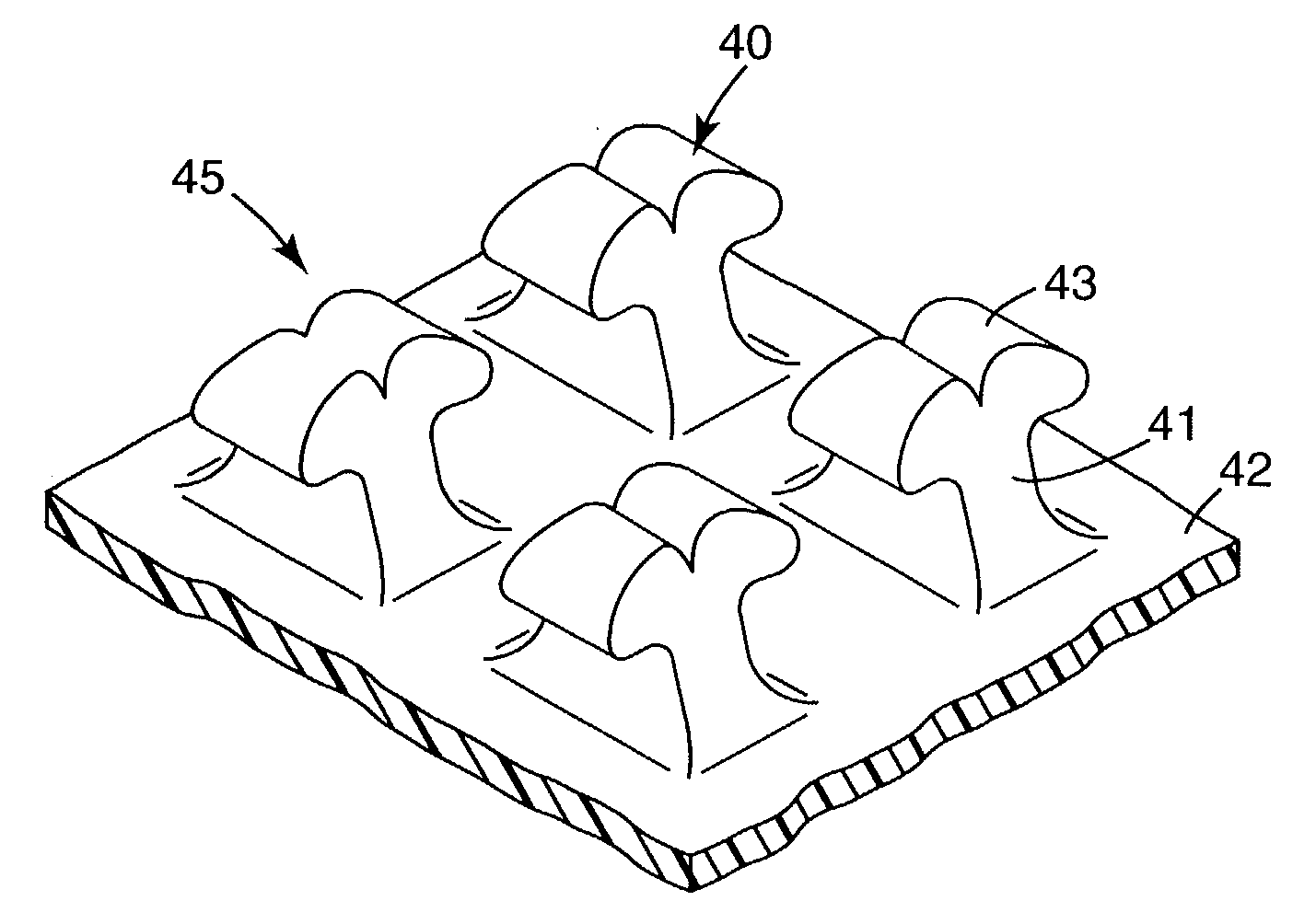
stretch ratio of about 4 to 1, preferably between a first pair of nip rollers 60 and 61 and a second pair of nip rollers 62 and 63 driven at different surface speeds. Optionally, the strip 50 can also be transversely stretched to provide biaxial orientation to the base 53. Roller 61 is preferably heated to heat the base 53 prior to stretching, and the roller 62 is preferably chilled to stabilize the stretched base 53. Stretching causes spaces between the cut portions 57 of the ribs 54, which then become the hook portions or members 14 for the completed hook fastener portion 10. The formed hook members are then heat treated preferably by a non-contact heat source 64. The temperature and duration of the heating should be selected to cause shrinkage or thickness reduction of at least the head portion by from 5 to 90 percent. The heating is preferably accomplished using a non-contact heating source which can include radiant, hot air, flame, UV, microwave, ultrasonics or focused IR heat lamps. This heat treating can be over the entire strip containing the formed hook portions or can be over only a portion or zone of the strip. Or different portions of the strip can be heat treated to more or less degrees of treatment. In this manner, it is possible to obtain on a single strip hook containing areas with different levels of performance without the need to extrude different shaped rib profiles. This heat treatment can change hook elements continuously or in gradients across a region of the hook strip. In this manner, the hook elements can differ continuously across a defined area of the hook member. Further, the hook density can be the same in the different regions coupled with substantially the same film backing caliper or thickness (e.g., 50 to 500 microns). The caliper can easily be made the same as the hook strip will have the same basis weight and same relative amount of material forming the hook elements and backing in all regions despite the difference in the shape of the hooks caused by the subsequent heat treating. The differential heat treatment can be along different rows or can cut across different rows, so that different types of hooks, such as hooks having different hook thicknesses, can be obtained in a single or multiple rows in the machine direction or the lengthwise direction of the hook strip. The heat treatment can be performed at any time following creation of the hook element, such that customized performance can be created without the need for modifying the basic hook element manufacturing process.
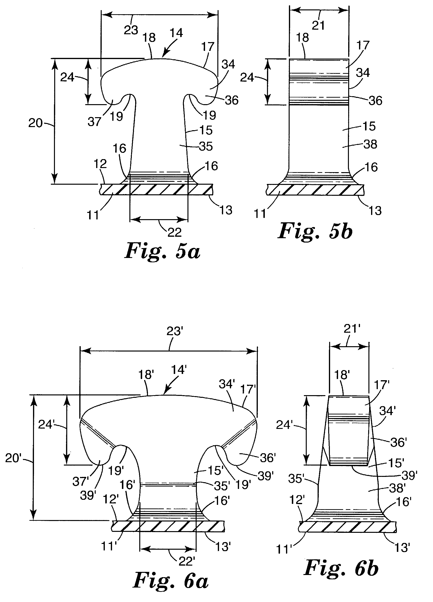
[0035] The heat treatment is generally carried out at a temperature near or above the polymer melt temperature. As the heat gets significantly above the polymer melt temperature, the treatment time decreases so as to minimize any actual melting of the polymer in the hook head portion or top of the projection. The heat treatment is carried out at a time sufficient to result in reduction of the thickness of the hook head, and / or stem, but not such that there is a significant deformation of the backing or melt flow of the hook head portion or top of the projection. Heat treatment can also result in rounding of the hook head portion edges, improving tactile feel for use in garment applications.
[0036] Unexpectedly it has been discovered, that for high performance microhook engagement with certain low cost or low loft loop fabrics, that this heat treatment substantially increases engagement of the microhooks to the loop fabrics. A particularly preferred novel, microhook member producible by the invention method has been discovered where the hook members have a height of less than 1000 .mu.m, preferably from 300 to 800 .mu.m, and at least a head portion with a thickness of from 50 to 200 .mu.m, preferably 50 to 180 .mu.m. The other dimensions for this improved microhook include a stem width, as defined above, of from 50 to 500 .mu.m, a head portion width of from 100 to 800 .mu.m, and an arm droop of from 50 to 700 .mu.m, preferably 100 to 500 .mu.m, and a hook density of at least 50 and preferably from about 70 to 150, up to 300, hooks per square centimeter. This novel microhook hook portion exhibits improved overall performance to a variety of low loft loop fabrics.

Problems solved by technology

However, they are generally expensive and coarse to the touch.
This generally inherently limits the individual hooks to those capable of engaging only in a single direction while also limiting the strength of the engaging head portion of the hook element.
However, a limitation with this method of manufacture is in forming hook structures that are extremely narrow in the extrusion direction of the ribs or the cut direction.
Cutting the formed ribs at very closely spaced intervals is difficult at commercially acceptable production speeds.
Further, when the cut length is extremely closely spaced the previously cut portions of the ribs tend to fuse due to the heat created by the cutting operation.
The end result is a hook thickness that can either, not be economically produced directly, or cannot be produced at all by conventional methods.
Biaxial orientation also reduces the hook density to the desired range for low density hook application.

Method used


Image

  • Heat treated profile extruded hook
  • Heat treated profile extruded hook
  • Heat treated profile extruded hook

Examples


example 1

[0065] The web of comparative example C1 was subjected to a non-contact heat treatment on the hook side of the web by passing said web underneath a 36 cm wide ribbon flame burner Aerogen (Alton Hampshire, UK) at a speed of 90 meter / minute with a burner to film gap of 8 mm. The flame power was 74 kJ / hour. The smooth base film side of the web was supported on a chill roll maintained at approximately 18.degree. C. The general profiles of the resulting heat treated hook are depicted in FIGS. 6a and 6b. The performance of the hook material web against nonwoven loop material `A` was measured using a 135.degree. peel test with the results shown in Table 1 below. The peel force of the heat-treated web was approximately 63% greater than the non-heated Comparative Example 1.

example 2

[0066] The web of Comparative Example C1 was subjected to a non-contact heat treatment on the hook side of the web by passing said web underneath a bank of 6-1000 watt 1 micron wavelength infrared bulbs at a speed of 2.1 meter / min. The hook to bulb spacing was approximately 2.5 cm. The smooth base film side of the web was supported on a chill roll maintained at approximately 66.degree. C. The general profiles of the resulting heat treated hook are depicted in FIGS. 7a and 7b. The performance of the hook material web against nonwoven loop material `A` was measured using a peel test with the results shown in Table 1 below. The 1350 peel force of the heat-treated web was approximately 206% greater than the non-heat treated Comparative Example C1.

example 3

[0068] The web of Comparative Example C2 was subjected to a non-contact heat treatment on the hook side of the web by passing said web underneath a bank of 6-2000 watt 1 micron wavelength infrared bulbs at a speed of 3.0 meter / min. The hook to bulb spacing was approximately 1.6 cm. The smooth base film side of the web was supported on a chill roll maintained at approximately 66.degree. C. The performance of the hook material web against nonwoven loop material `A` was measured using a peel test with the results shown in Table 1 below. The 135.degree. peel force of the heat-treated web was approximately 37% greater than the non-heat treated Comparative Example C2.


PUM

PropertyMeasurementUnit
Lengthaaaaaaaaaa
Lengthaaaaaaaaaa
Fractionaaaaaaaaaa

Abstract

A method for forming a unitary polymeric projection or fastener comprising a thin, strong flexible backing, and a multiplicity of thin spaced hook members projecting from the upper surface of the unitary backing the method generally including extruding a thermoplastic resin through a die plate which die plate is shaped to form a base layer and spaced ridges, ribs or hook elements projecting above a surface of the base layer. When the die forms the spaced ridges or ribs the cross sectional shape of the hook members are formed by the die plate while the initial hook member thickness is formed by transversely cutting the ridges at spaced locations along their lengths to form discrete cut portions of the ridges. Subsequently longitudinal stretching of the backing layer (in the direction of the ridges on the machine direction) separates these cut portions of the ridges, which cut portion then form spaced apart hook members. The extruded hook members or cut rib hook members are then heat treated resulting in shrinkage of at least a portion of at least the hook head portion thickness by from 5 to 90 percent, preferably 30 to 90 percent.

Description

[0001] This is a continuation-in-part of U.S. application Ser. No. 10 / 316,686, filed Dec. 11, 2002 which is a continuation-in-part of U.S. application Ser. No. 10 / 214,051, filed Aug. 7, 2002 which is a continuation-in-part of U.S. application Ser. No. 10 / 050,403, filed Jan. 15, 2002, the disclosures of which are incorporated herein by reference.BACKGROUND AND SUMMARY[0002] The present invention concerns molded hook fasteners for use with hook and loop fasteners.[0003] There are a variety of methods known to form hook materials for hook and loop fasteners. One of the first manufacturing methods for forming hooks involved weaving loops of monofilaments into a fibrous or film backing or the like followed by cutting the filament loops to form hooks. These monofilament loops were also heated to form headed structures such as disclosed in U.S. Pat. Nos. 4,290,174; 3,138,841 or 4,454,183. These woven hooks are generally durable and work well for repeated uses. However, they are generally e...

Claims


Application Information

Patent Timeline
IPC IPC(8): A61F13/49A44B18/00A61F13/56B29C48/00B29C48/08
CPCA44B18/0065Y10T24/2792B29C47/0021B29C47/00B29C48/00B29C48/08
Inventor AUSEN, RONALD W.UNRUH, WILLIAM C.MILLER, PHILIPSETH, JAYSHREE
Owner 3M INNOVATIVE PROPERTIES CO
Why Eureka
Try Eureka