A device and method for thermal imaging of a living mammal body section

Active Publication Date: 2020-06-18
H A W VAN WEL +1
View PDF0 Cites 0 Cited by
  • Summary
  • Abstract
  • Description
  • Claims
  • Application Information

AI Technical Summary

Benefits of technology

This is an improved device and method for screening living mammal body sections to detect potential tumorous or tumorous regions. The device uses PET or BoPET material, which is a strong and highly inert material that does not interact with the skin of the body section being investigated. The device can automatically detect and control the thermal energy transfer to the body section, preventing heating or cooling down of the body section prior to the imaging process. The device can also automatically assess the registration results and produce reliable and repeatable results, without requiring trained personnel. The data obtained can be subjected to various data filtering and analysis techniques.

Problems solved by technology

It has been observed that prior art detection methods and systems based on thermospatial imaging and thermography are less adequate for distinguishing and detecting irregularities in an examined body section.
A wrong choice of foil may either result in an excessive coloration or in a too less coloration, both of which do not allow to monitor and detect specific areas of interest.
The relative high starting temperature of thermographic detection, among others, makes thermographic registration methods too less specific for detecting anomalies in cells of living bodies, such as tumours, based on the difference in thermal energy emanating from tumour cells compared to healthy cells or tissue.
These methods are also too insensitive for detecting tumours deep beneath the surface or skin of the body section and for detecting grades of vascularity, for example.
This examining method is, however, invasive, relatively time consuming and expensive, and as such not suitable for a relatively quick and easy to use screening for tumour cells, for example.

Method used


Image

  • A device and method for thermal imaging of a living mammal body section
  • A device and method for thermal imaging of a living mammal body section
  • A device and method for thermal imaging of a living mammal body section

Examples


Embodiment Construction

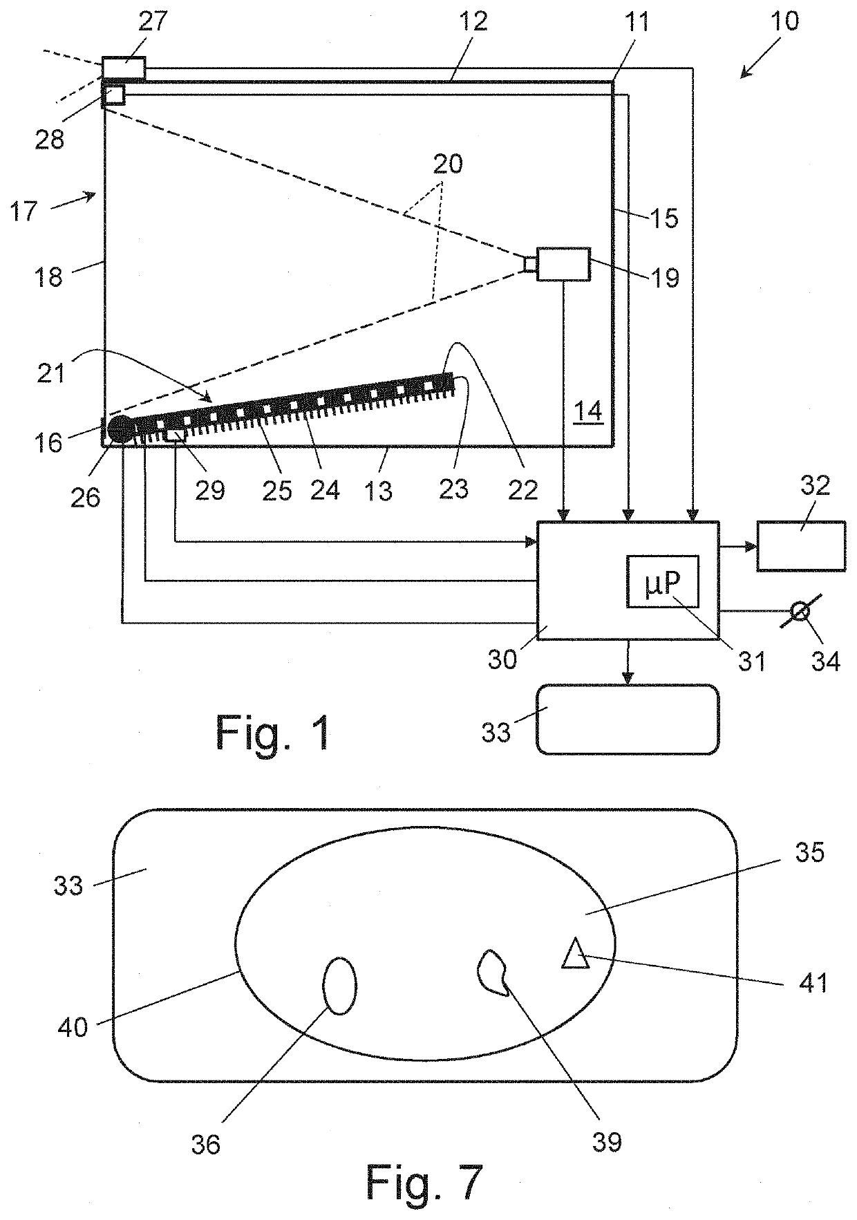
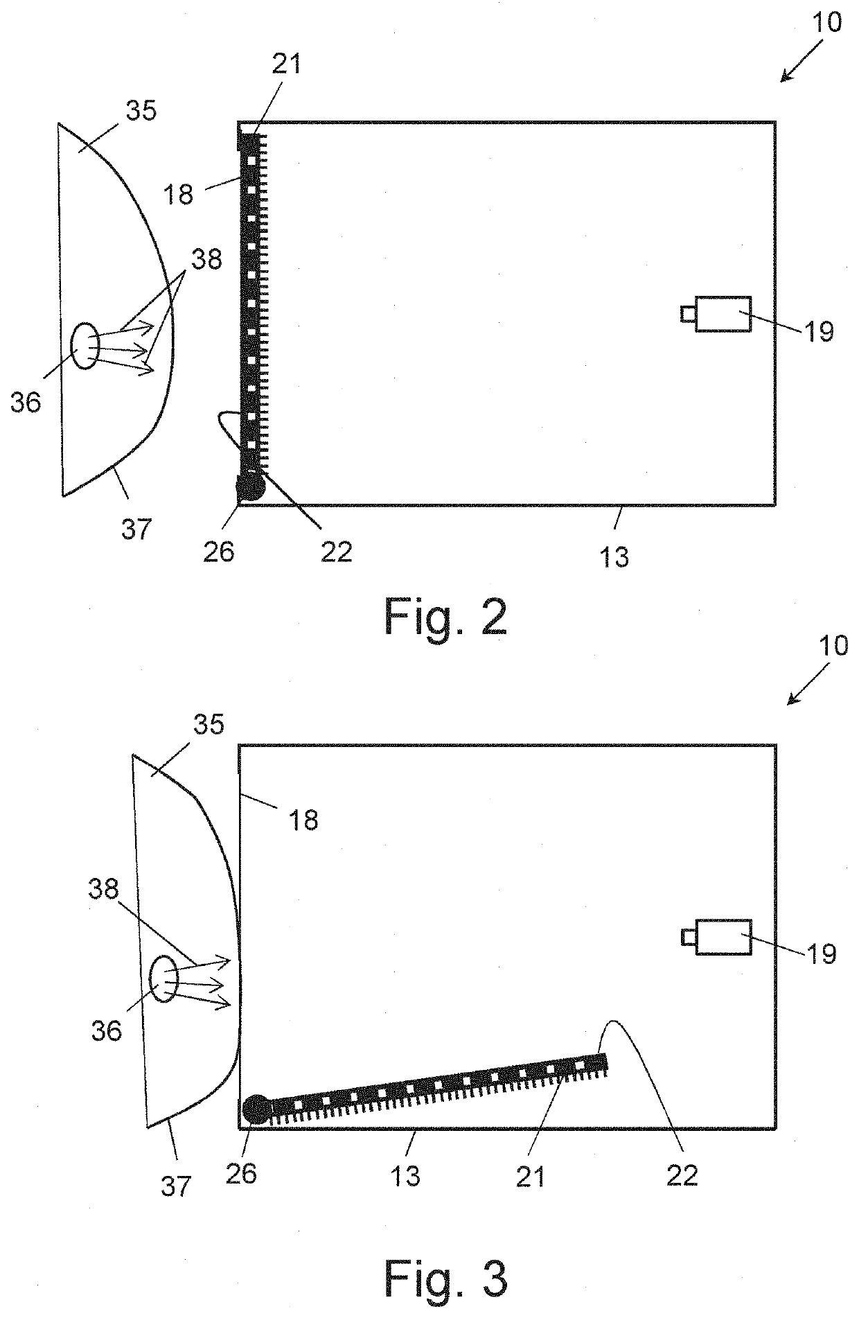
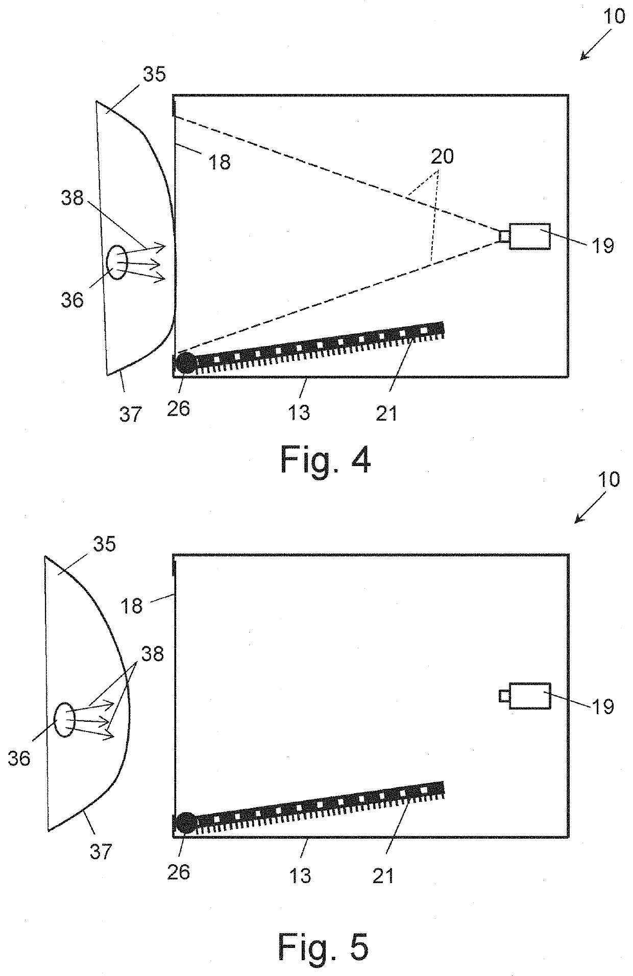
[0064]FIG. 1 shows a cross-sectional view of an embodiment of a device 10 for obtaining thermal images of a living mammal body section in accordance with the invention. The device 10 has a housing 11, generally comprised of a top part or wall 12, an opposing bottom part or wall 13, two opposing side parts or walls 14, a back part or wall 15 and an open front part or wall 16, when viewed in the operating position of the device 10 as shown FIG. 1. An opening 17 of the front part 16 is covered by a thermal energy storage surface structure 18, such as a thermal energy storage plate or foil, having a flat or curved surface shape, in particular an opaque thermal energy storage plate or foil, for contacting the body section to be imaged.

[0065]In the housing 11, near the back part 15 thereof, a thermal sensor 19 is arranged having field of view 20 direct towards the thermal energy storage surface structure 18, for obtaining thermal images reflecting the storage of thermal energy from at lea...


PUM


Abstract

A device of and a method for obtaining thermal images of a living mammal body section. The device comprises a thermal energy storage surface structure for contacting the body section. In a calibration mode of operation, the thermal energy storage surface structure is brought at a reference temperature by transferring thermal energy to the thermal energy storage surface structure from a thermal energy transfer module that is controlled by a control circuit for restraining thermal energy transfer by the thermal energy transfer module in the presence of the body section at the thermal energy storage surface structure. In a registration mode of operation, by a thermal sensor, thermal images reflecting thermal energy storage over at least a portion of the thermal energy storage surface structure are obtained, with the body section contacting the thermal energy storage surface structure. From a series of time consecutive thermal images obtained, a region of interest is determined, based on storage of thermal energy by the thermal energy storage surface structure.

Description

TECHNICAL FIELD[0001]The present invention relates generally to the field of thermal imaging and, more particularly, to a device and method for thermal imaging of a body section of a living mammal, in particular a human being, for determining a region of interest of such body section based on thermal parameters obtained from thermal imaging data.BACKGROUND[0002]Living biological bodies are subject to metabolic activity. Metabolic activity refers to the set of chemical reactions that maintain life in any organism. Metabolic activity involves the transformation of energy and matter in the body, two elements that always are present for life to be sustained.[0003]Metabolism is associated with heat production. It has been observed that the metabolism of healthy cells of a living body differs from the metabolism of tumour cells—either benign or malignant tumour cells such as cancer cells—in that tumour cells comprise a higher amount of thermal energy. This thermal energy is transferred fr...

Claims


Application Information

Patent Timeline
IPC IPC(8): A61B5/01A61B5/00
CPCA61B2562/0271A61B5/683A61B5/01A61B5/6843A61B5/004A61B5/4866A61B5/015A61B5/00
Inventor KLEEVEN, ANTONIUS MARIA
Owner H A W VAN WEL
Why Eureka
Try Eureka