Infrared thermometer and detecting head component thereof

Inactive Publication Date: 2009-03-12
RADIANT INNOVATION INC
View PDF23 Cites 0 Cited by
  • Summary
  • Abstract
  • Description
  • Claims
  • Application Information

AI Technical Summary

Benefits of technology

[0008]The present invention discloses an infrared thermometer and a novel detecting head component thereof. The detecting head component in the present invention significantly improves the comfortableness of using the thermometer. The detecting head component includes a sleeve unit. The sleeve unit is ma

Problems solved by technology

The sleeve unit is made by elastomer m

Method used


Image

  • Infrared thermometer and detecting head component thereof
  • Infrared thermometer and detecting head component thereof
  • Infrared thermometer and detecting head component thereof

Examples


Example

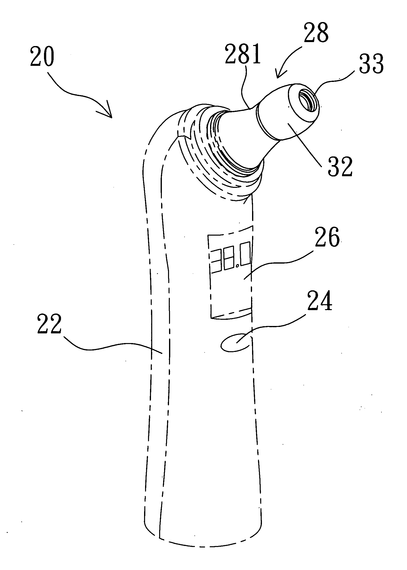
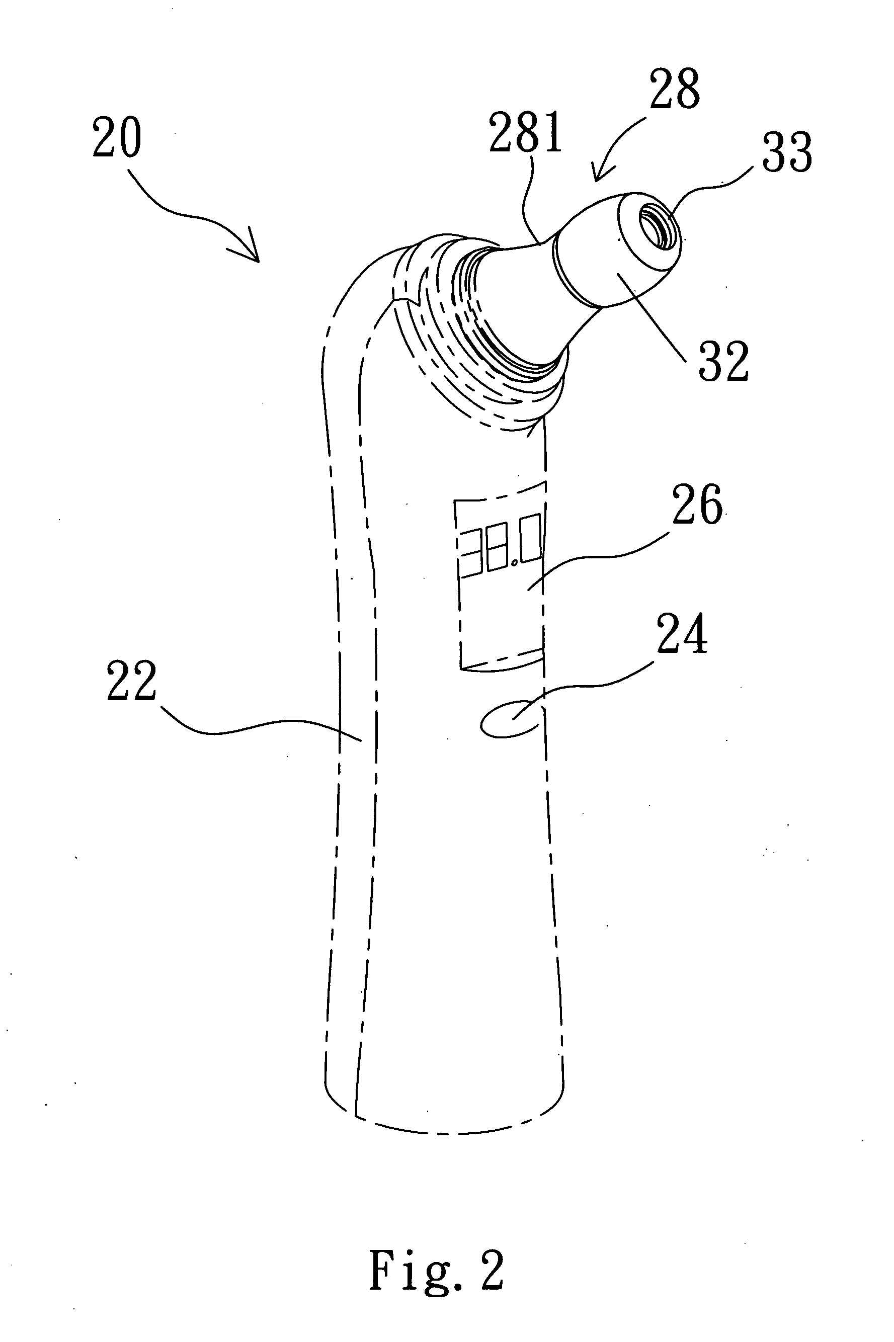
[0016]The present invention discloses an infrared thermometer and a novel detecting head component thereof. The detecting head component in the present invention significantly improves the comfortableness of using the thermometer. Please note that, the following description of embodiment is based on the infrared ear thermometer. However, the infrared ear thermometer is only an example of the present invention, and is not meant to be taken as limitations. That is, as will be easily observed by a personal of ordinary skill in the art, other embodiments of the present disclosure (e.g. infrared forehead thermometer) are also possible.

[0017]Please refer to FIG. 2 in conjunction with FIG. 3. FIG. 2 is a diagram schematically showing an infrared ear thermometer according to the present invention. And FIG. 3 shows a block diagram of the connection for each component in the infrared ear thermometer according to the present invention. As shown in FIG. 2, the infrared ear thermometer 20 in the...


PUM


Abstract

The present invention discloses an infrared thermometer and a detecting head component thereof. The novel detecting head component is located on the top of the infrared thermometer. The detecting head component includes a shell, n infrared detector inside the shell, and a sleeve unit, coupled to the part of the shell which contacts with a measuring object. The infrared thermometer in the present invention can increase the comfortableness of user during using the infrared thermometer.

Description

BACKGROUND OF THE INVENTION[0001]1. Field of the Invention[0002]The invention relates to an infrared thermometer and a detecting head component thereof, and more particularly, to an infrared thermometer and a detecting head component to increase the comfortableness of user during using the infrared thermometer.[0003]2. Description of the Related Art[0004]The infrared ear or forehead thermometers are well known in the art and commonly used to determine the body temperature based on the infrared radiation technology. The advantage of utilizing the infrared thermometer lies in the almost accurate result, and easy and fast measure process. With the accelerated development of the infrared radiation technology, the infrared thermometer becomes one of the most important meters in nowadays.[0005]Please refer to FIG. 1. FIG. 1 is a diagram schematically showing an ear thermometer of a conventional technology. As shown in FIG. 1, the conventional ear thermometer 10 includes a main body 12 and...

Claims


Application Information

Patent Timeline
IPC IPC(8): G01J5/00G01K1/08
CPCG01J5/02G01J5/049G01J5/04G01J5/021
Inventor WENG, VINCENTLIN, KEVIN
Owner RADIANT INNOVATION INC
Why Eureka
Try Eureka