
Machining method and apparatus

Active Publication Date: 2016-11-03
BAE SYSTEMS PLC
View PDF5 Cites 2 Cited by
  • Summary
  • Abstract
  • Description
  • Claims
  • Application Information

AI Technical Summary

Benefits of technology

The patent text suggests that it is beneficial to have a pre-programmed process for changing tools that reduces the workload and cost for engineers. This is because the process helps to prevent collisions and improve efficiency.

Problems solved by technology

The present inventors have realized that for some objects and fixture systems, especially those having high curvature or complex shapes such as an aircraft center arch panel, standard retractions of the cutting apparatus from the object surface tend to introduce a high risk of the cutting apparatus impacting with the object and / or support fixture.
Such collisions may result in damage to the cutting apparatus and / or the object being machined.

Method used


Image

  • Machining method and apparatus
  • Machining method and apparatus
  • Machining method and apparatus

Examples


Embodiment Construction

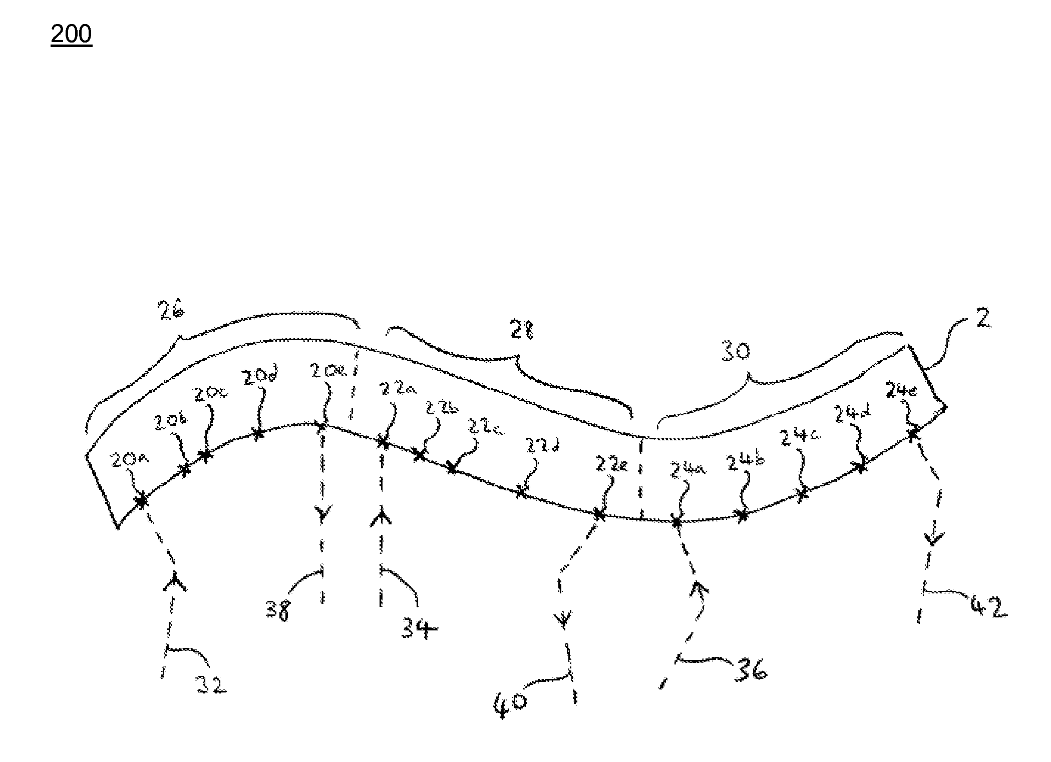
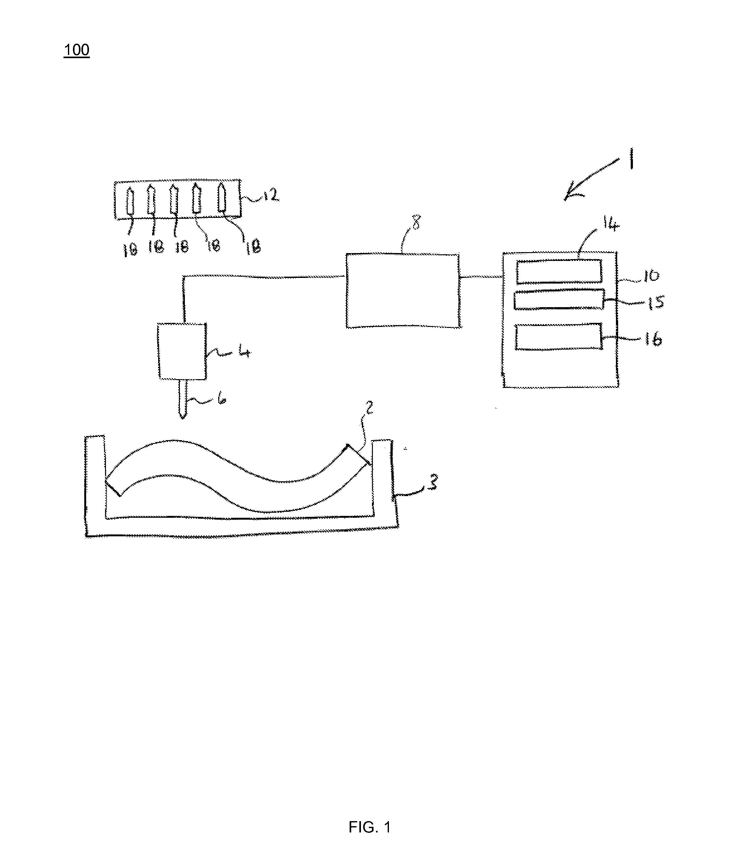
[0025]FIG. 1 is a schematic illustration (not to scale) of an example of an environment 1 in which an embodiment of a drilling process is performed. The drilling process is described in more detail later below with reference to FIG. 3.

[0026]The terminology “drilling process” is used herein to refer to any type of drilling, cutting, or machining process including, but not limited to, fusion cutting, flame cutting, sublimation cutting, drilling a hole, countersinking (a pre-drilled hole), reaming, orbital drilling, etc.

[0027]In this embodiment, the environment 1 comprises an aircraft panel 2 to be drilled, a fixture system 3, a robot arm 4 comprising a drill bit 6, a controller 8, a processor 10, and a tool storage 12.

[0028]The aircraft panel 2 is made of carbon fiber. The aircraft panel 2 is to be fixed to an airframe of an aircraft to form an external skin of the aircraft.

[0029]The fixture system 3 comprises a frame in which the aircraft panel 2 is fixed, for example, using a plural...


PUM


Abstract

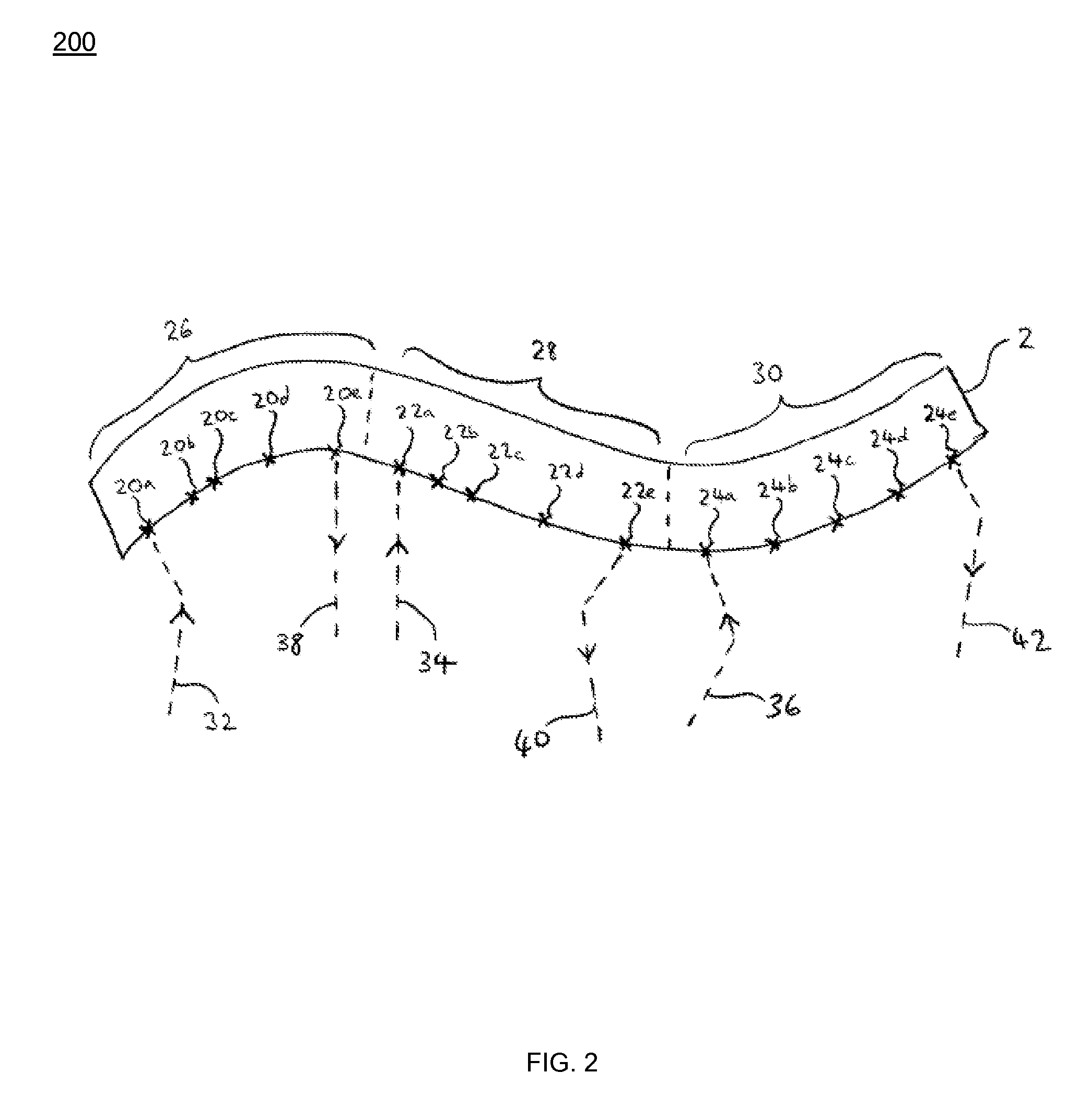
Disclosed is a method and apparatus for machining a workpiece (2). The method comprises specifying a path along which a cutting tool (6) is moved during machining the workpiece (2), the path comprising segments (26); defining, for each segment (26), an exit point on that segment (26); defining, for each segment (26), an exit path (38) from the exit point of that segment (26) to a point remote from the workpiece (2); performing a machining process including moving the cutting tool (6) along the tool path and machining the workpiece (2); and, during the machining process, when one or more criteria are satisfied: interrupting the machining process and, without machining the workpiece (2), moving the cutting tool (6) to the exit point of the current segment (26) and then along the exit path (38) of the current segment (26).

Description

FIELD OF THE INVENTION[0001]The present invention relates to the machining of workpieces.BACKGROUND OF THE INVENTION[0002]In the field of aircraft construction, cutting tools, such as drill bits, are used to perform machining operations on aircraft parts. For example, predrilled holes in aircraft panels may be countersunk so that fasteners used to fasten the aircraft panel to the structure are flush with a surface of the panel (e.g. the outer surface of the aircraft).[0003]Due to regular operation, cutting tools wear which may cause them to fail. It is desirable to change cutting tools prior to the failure of cutting tools.SUMMARY OF THE INVENTION[0004]In order to change a cutting tool, typically the device to which the cutting tool is attached (for example, a robot arm) has to be moved away from the object being machined and any fixture system supporting the object. The present inventors have realized that for some objects and fixture systems, especially those having high curvature...

Claims


Application Information

Patent Timeline
IPC IPC(8): G05B19/31G05B19/402
CPCG05B19/31G05B2219/49372G05B19/402B25J9/1676G05B19/4061G05B19/4065G05B19/4067G05B2219/49146G05B2219/50109G05B2219/50111Y02P90/02
Inventor CARBERRY, JONATHAN MICHAELCOOK, AUSTIN JAMESMCMILLAN, DAVIDDERECICHEI, ARON
Owner BAE SYSTEMS PLC
Learn More