Head positioning device

Inactive Publication Date: 2005-07-28
FROELICH MICHAEL
View PDF15 Cites 60 Cited by
  • Summary
  • Abstract
  • Description
  • Claims
  • Application Information

AI Technical Summary

Problems solved by technology

However, standard pillows and blankets are typically ineffective at maintaining the patient's head in the sniffing position while the patient is being intubated.
However, these maneuvers to improve

Method used


Image

  • Head positioning device
  • Head positioning device
  • Head positioning device

Examples


Embodiment Construction

[0017] The present invention now will be described more fully with reference to the accompanying drawings, in which some, but not all embodiments of the invention are shown. As will be understood by one skilled in the relevant field, this invention may be embodied in many different forms and should not be construed as limited to the embodiments set forth herein. Rather, these embodiments are provided so that this disclosure will satisfy applicable legal requirements. Like numbers refer to like elements throughout.

I. Overview of Head Positioning Device

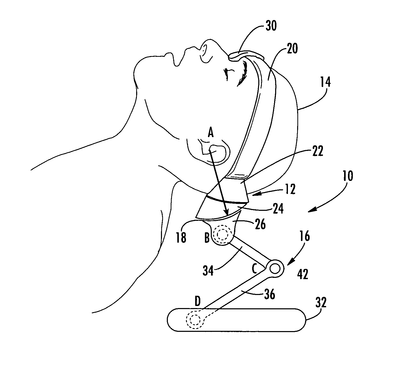
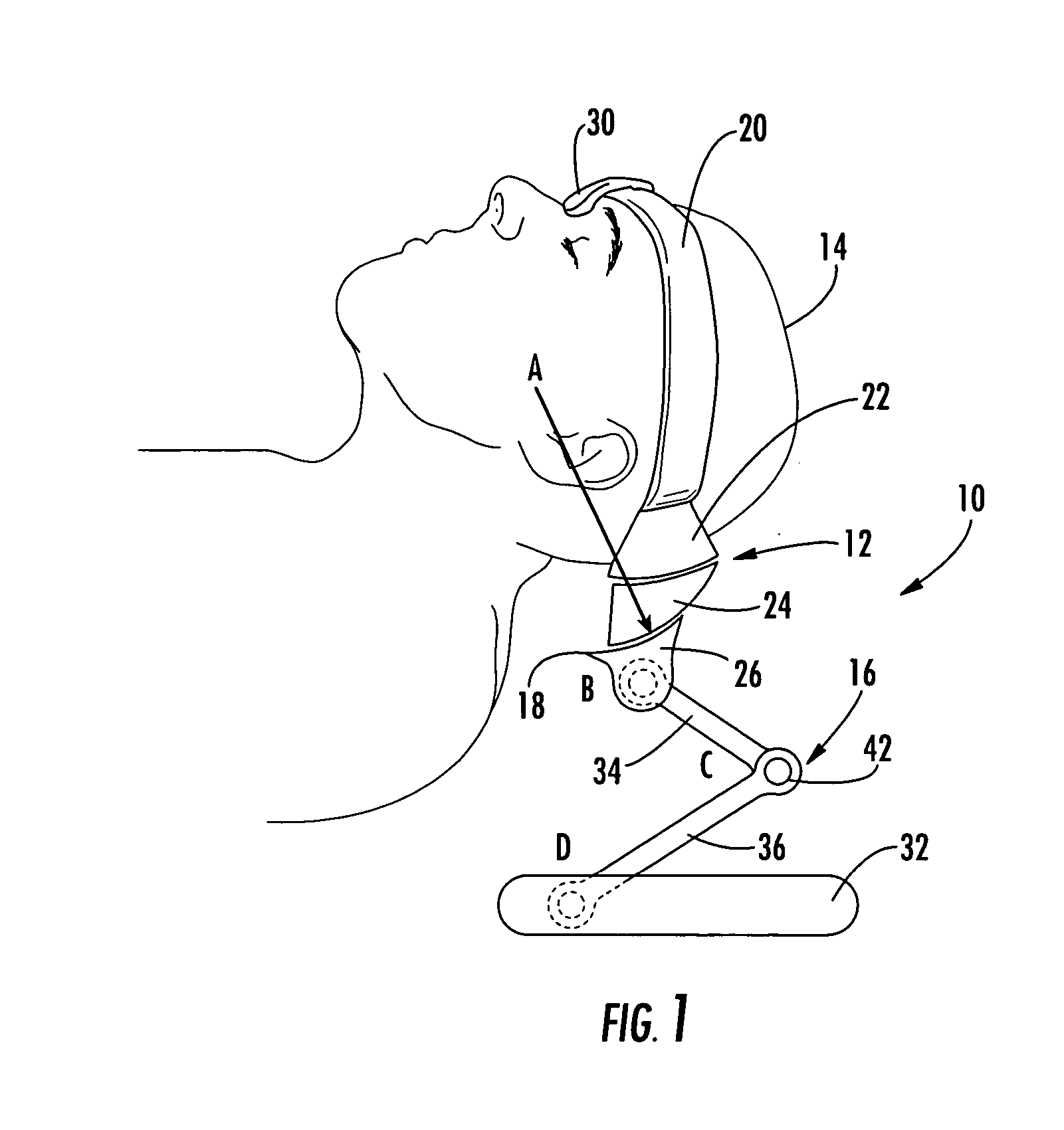
[0018]FIG. 1 depicts a head positioning device 10 according to one embodiment of the present invention. As may be understood from this figure, in this embodiment, the head positioning device 10 comprises a head support 12 for supporting a patient's head 14, and an elevating mechanism 16 for positioning the head support in a predetermined position. In this embodiment, the head support 12 and the elevating mechanism 16 are connected by...


PUM


Abstract

A head positioning device comprising: (A) a head support that is configured for supporting a patient's head; and (B) a sliding joint that is connected to allow the head support to be moved about a virtual axis of rotation while the head support is supporting the patient's head, wherein the virtual axis of rotation is spaced apart from the sliding joint. The head positioning device may include a head restraint for maintaining the patient's head in a substantially fixed relation to the head support as the head support is moved about the virtual axis of rotation. In one embodiment, the head restraint comprises a hook member that is configured for hookedly engaging a curved portion of the patient's face.

Description

BACKGROUND OF THE INVENTION [0001] Endotracheal intubation and laryngoscopy are techniques that are often practiced by anesthesiologists in, for example, operating rooms, intensive care units, and emergency rooms. Most anesthesia textbooks recommend moving a patient's head into the “sniffing position” before intubating the patient. When a patient's head is in the sniffing position, typically: (1) the patient's head is elevated; (2) the patient's neck is extended; and (3) the patient's axis of vision is relatively well aligned with the axis of the patient's glottis. More specifically, the sniffing position is typically achieved when the oropharyngeal, laryngeal, and tracheal axes of the patient's head and neck are at least substantially aligned. Placing a patient's head into the sniffing position is desirable to give the practitioner intubating the patient as clear of a view as possible of the patient's glottis and vocal cords to successfully guide the intubation tube into the patien...

Claims


Application Information

Patent Timeline
IPC IPC(8): A61B19/00A61G13/12A61M16/04
CPCA61B19/203A61G13/12A61M16/0488A61G13/1215A61G13/121A61B90/14
Inventor FROELICH, MICHAEL
Owner FROELICH MICHAEL
Why Eureka
Try Eureka