Portable lifting device

a technology of lifting device and stairwell, which is applied in the direction of lifting device, lifting equipment, load-engaging elements, etc., can solve the problems of waste of customer's time, waste of assistant's time and costly to customers, and delay in servicing the air conditioner unit, etc., to achieve sufficient shear and tensile strength, the effect of raising and lowering the load

Inactive Publication Date: 2005-07-28
TOPPER JOHN
View PDF17 Cites 1 Cited by
  • Summary
  • Abstract
  • Description
  • Claims
  • Application Information

AI Technical Summary

Benefits of technology

[0007] Accordingly, the present invention is a portable lifting device for use on a temporary basis to lift objects up to, or to lower down from, an elevated height, particularly a roof of a multi-story building. The present invention is particularly suited for use on small multi-storied building requiring the need to raise or lower bulky cumbersome, but lightweight cargo between the ground and the roof of a two or three story building. However, the portable lifting device of the present invention is not limited to bulky, cumbersome, lightweight cargo and may be used with other kinds of cargo, with buildings of different heights or raising and lowering cargo between floors of a multi-storied building.
[0013] In other embodiments, the top panel includes a concave depression with the entry hole positioned at the bottom of the depression. The concave depression may help guide the bob toward the entry hole. The concave depression also necessitates physical removal of the bob from the elongated slot by the user to prevent inadvertent removal of the bob from the catch while the portable lifting device is used to raise and lower the load.
[0014] In some embodiments, the bob has a cylindrical body with a cylindrical shank extending centrally from one end; the shank being suitably sized to be received by the elongated slot. The body and shank should be constructed of material selected to have sufficient shear and tensile strength for this purpose, and should be sufficiently heavy to freely fall through the entry hole. The diameter of the cylindrical body is larger than the diameter of the shank, which defines an annular engaging shoulder about the shank. The annular engaging shoulder prevents passage of the cylindrical body through the elongated slot.
[0017] Upon manual positioning of the bob through the entry hole, the concave depression of the top surface assists the user in guiding the bob in an outwardly direction away from the entry hole as the bob travels the length of the elongated slot. The annular engaging shoulder contacts the bottom surface of the top panel. Once the bob is properly situated in the confining end of a slot, an object or objects to which the catch is attached may be lifted or lowered.

Problems solved by technology

The air filters are often bulky and difficult to carry in a stairwell.
Having an assistant to carry the filters can be a wasteful use of the assistant's time and costly to the customer.
Depending on the size and quantities of the air filters, it may take the service man several trips to bring all the filters to the roof causing delays in servicing the air conditioner unit.
In addition, small multi-story buildings oftentimes do not have elevators, or interior stairwells for transporting goods and other cargo.
These types of units may require a person to carry large cumbersome items up a large number of steeply inclined steps.
Typical goods and supplies carried in these situations, while oftentimes bulky and numerous, are usually lightweight.
Many pre-existing lifting devices attach to ladders and include the use of mechanical winches to raise and lower the loads, and many also include a number of moving parts, which may increase cost and reduce reliability.
The major deficiency with these pre-existing ladder attachments is there limited functionality.
These types of devices are not designed for use between the middle stories of a multi-storied building.
Furthermore, these types of devices are limited to the working length of the ladder.
These types of lifting devices are typically secured to the exterior surface of the building and are not practical for temporary use.
In addition, these types of devices require multiple personnel to assemble and disassemble and are not easily transported to various job sites.

Method used


Image

  • Portable lifting device
  • Portable lifting device
  • Portable lifting device

Examples


Embodiment Construction

[0025] The following description is provide to enable any person skilled in the art to make and use the invention and sets forth the best mode presently contemplated by the inventor for carrying out his invention. Various modifications, however, will remain readily apparent to those skilled in the art, as generic principles of the present invention have been defined herein.

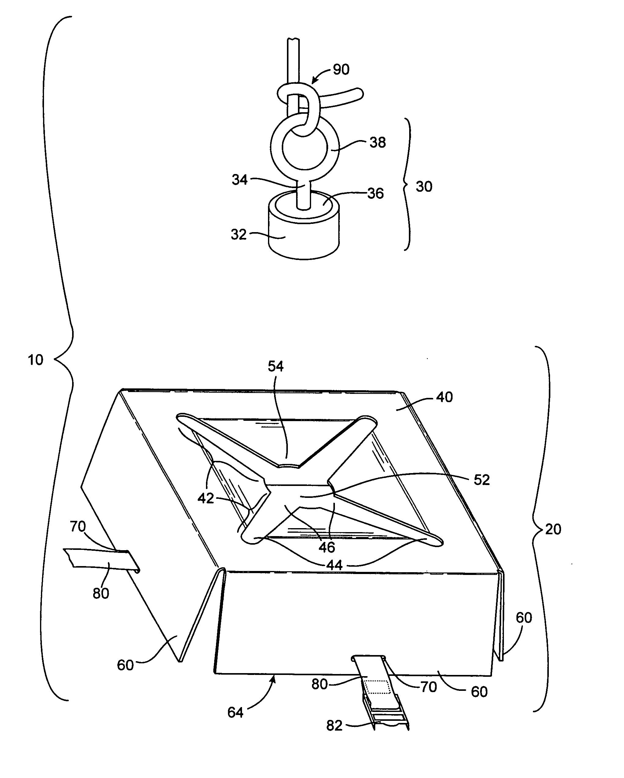
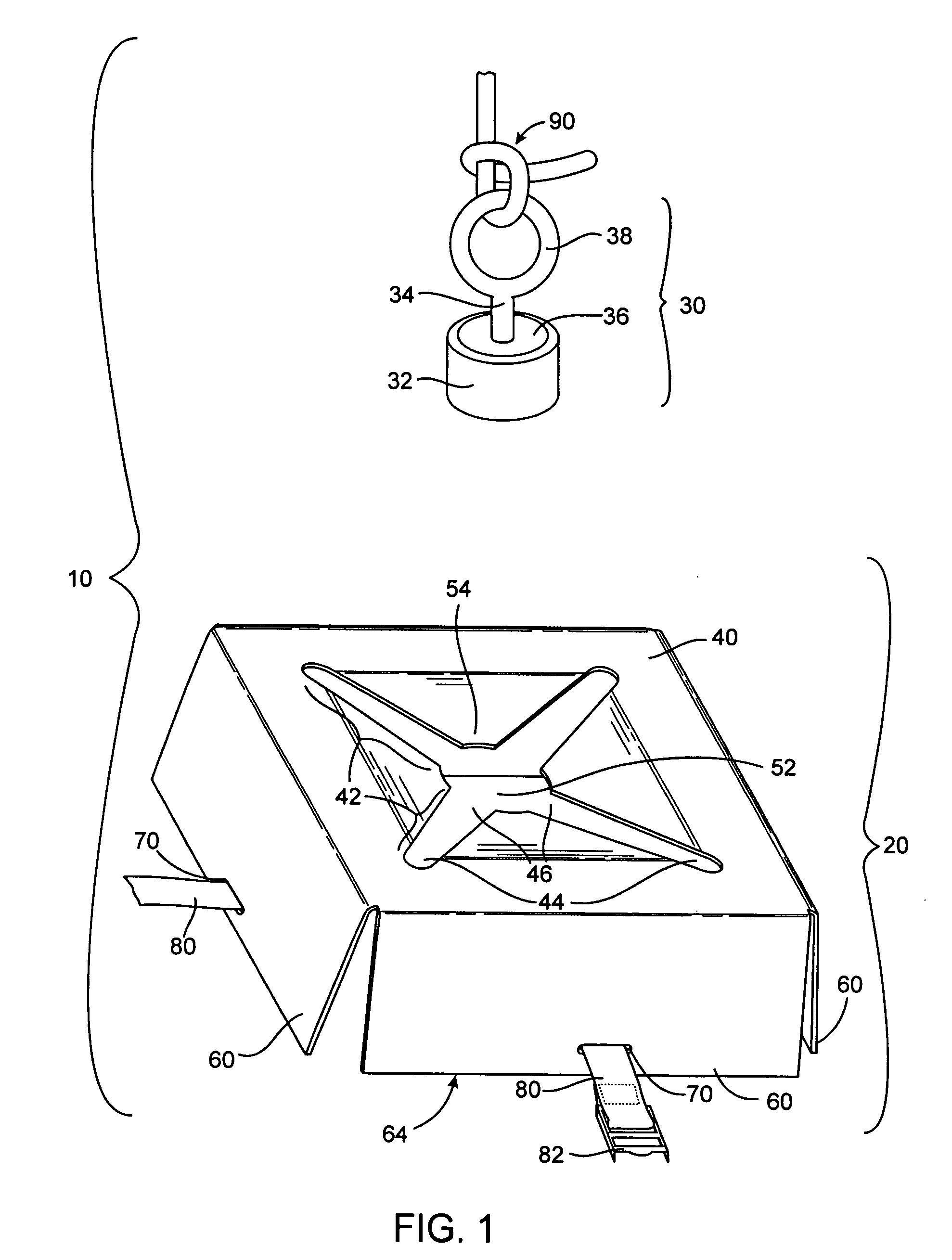
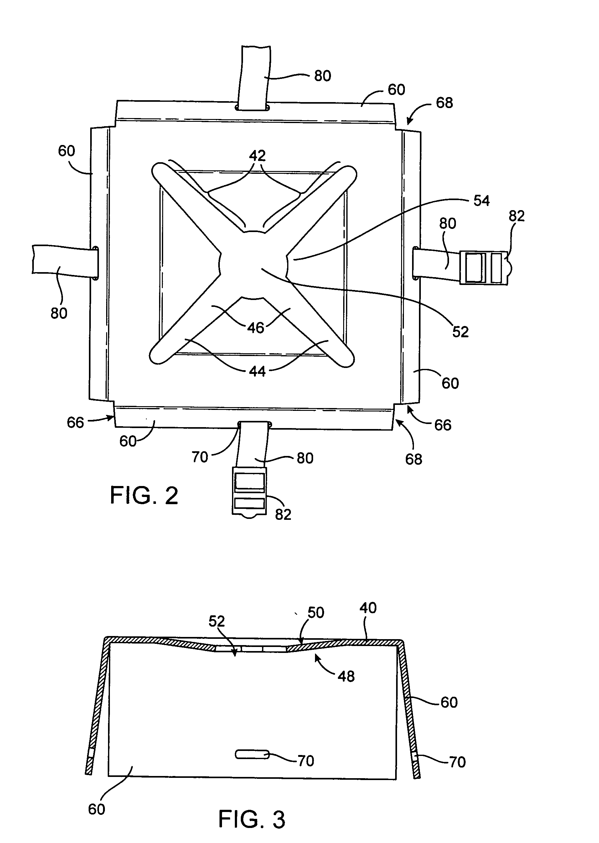
[0026] The present invention is a portable lifting device for use on a temporary basis to lift objects up to, or to lower down from, an elevated height, particularly a roof of a multi-story building. The portable lifting device of the present invention is particularly suited for use on small multi-storied building requiring the need to raise or lower bulky cumbersome, but lightweight cargo. The embodiments described herein are configured for raising and lowering bulky, cumbersome, lightweight cargo between the ground and the roof of a two or three story building. However, the portable lifting device of the presen...


PUM


Abstract

The present invention includes a portable lifting device for use on a temporary basis to lift objects up to, or to lower down from, an elevated height, particularly a roof of a multi-story building. The portable lifting device includes a catch, a bob, a securing means for attaching the catch to a load and a tether. The catch includes a top panel having at least on elongated slot an entry hole. The bob has a weighted body, a shank, and a tether anchor connected to the shank. The bob enters the catch through the entry hole wherein one the elongated slot receives the shank. When vertical tension is applied to the tether, the weighted body contacts the bottom surface of the top panel allowing the user to raise or lower the catch and attached load.

Description

FIELD OF INVENTION [0001] The present invention pertains to the movement of cargo, and more specifically to portable lifting devices for use on a temporary basis to lift objects up to, or to lower down from, an elevated height, particularly a roof of a multi-story building. BACKGROUND OF INVENTION [0002] There are many instances in which a load must be raised to or lowered from an elevated level, such as the roof of a building. For instance, air conditioner service men often carry air filters to the roof of a building using an internal stairwell. The air filters are often bulky and difficult to carry in a stairwell. Similarly, the used filters must be carried to the ground for disposal. When an air conditioner service man goes to a job site to replace air filters, he often goes alone. Having an assistant to carry the filters can be a wasteful use of the assistant's time and costly to the customer. Depending on the size and quantities of the air filters, it may take the service man s...

Claims


Application Information

Patent Timeline
Patent Type & Authority Applications(United States)
IPC IPC(8): B66C1/10
CPCB66C1/10
Inventor TOPPER, JOHN
Owner TOPPER JOHN
Why Eureka
Try Eureka