
Method and Apparatus for Load Dependent Speed Control of a Motor

a technology of variable speed control and motor, which is applied in the direction of electronic commutation motor control, motor/generator/converter stopper, dynamo-electric converter control, etc., can solve the problem that the current speed of the motor cannot be increased, the efficiency of the material handling system affecting the efficiency of the manufacturing process, and the motor no longer operates at peak efficiency. problem, to achieve the effect of raising or lowering the load

Active Publication Date: 2012-08-16
MAGNETEK
View PDF4 Cites 16 Cited by
  • Summary
  • Abstract
  • Description
  • Claims
  • Application Information

AI Technical Summary

Benefits of technology

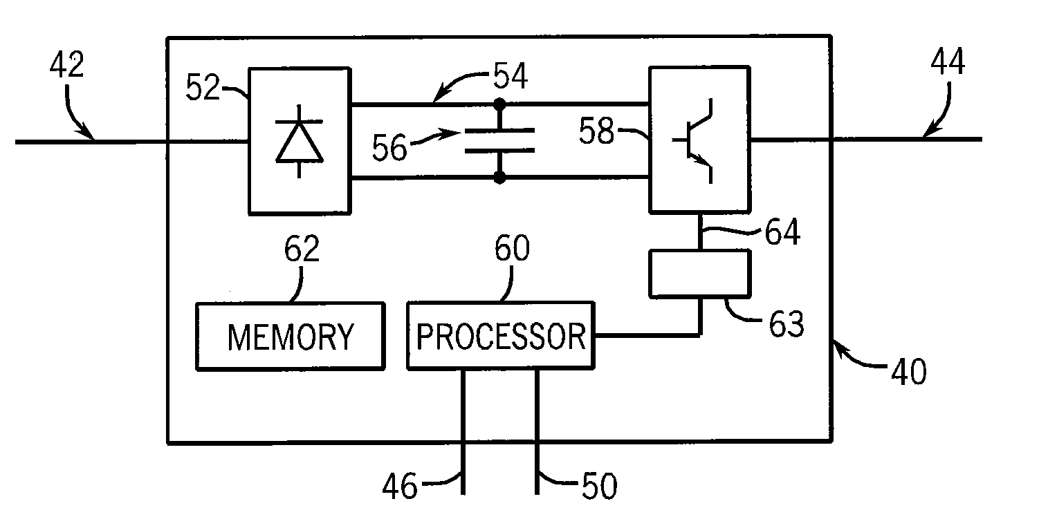
[0014]As yet another aspect of the invention, the power converter may also include an input configured to receive a speed feedback signal corresponding to a rotational speed of the motor. The control module further executes to periodically compare the speed feedback signal to a predetermined threshold, and if the speed feedback signal is greater than the predetermined threshold, the motor drive indicates a fault condition and stops rotation of the motor, but if the speed feedback signal is less than the predetermined threshold, the motor drive continues to rotate the motor at the new speed command.
[0015]According to yet another embodiment of the invention, a method of controlling a motor used to selectively raise or lower a load in a material handling system with a motor drive receives a command signal at the motor drive to begin rotation of the motor to either raise or lower the load. At a periodic interval, the following steps are repeated while the command signal is present at the motor drive. A magnitude of torque produced by the motor during rotation of the motor is obtained from a signal in the motor drive. A maximum rotational speed of the motor is determined as a function of the magnitude of torque produced by the motor, and the speed of the motor is controlled with the motor drive to rotate at the maximum rotational speed. Rotation of the motor is stopped when the command signal is removed from the motor drive. The measured torque in the motor drive may be filtered prior to determining the maximum rotational speed of the motor, and the maximum rotational speed of the motor may further be a function of the direction of rotation of the motor.
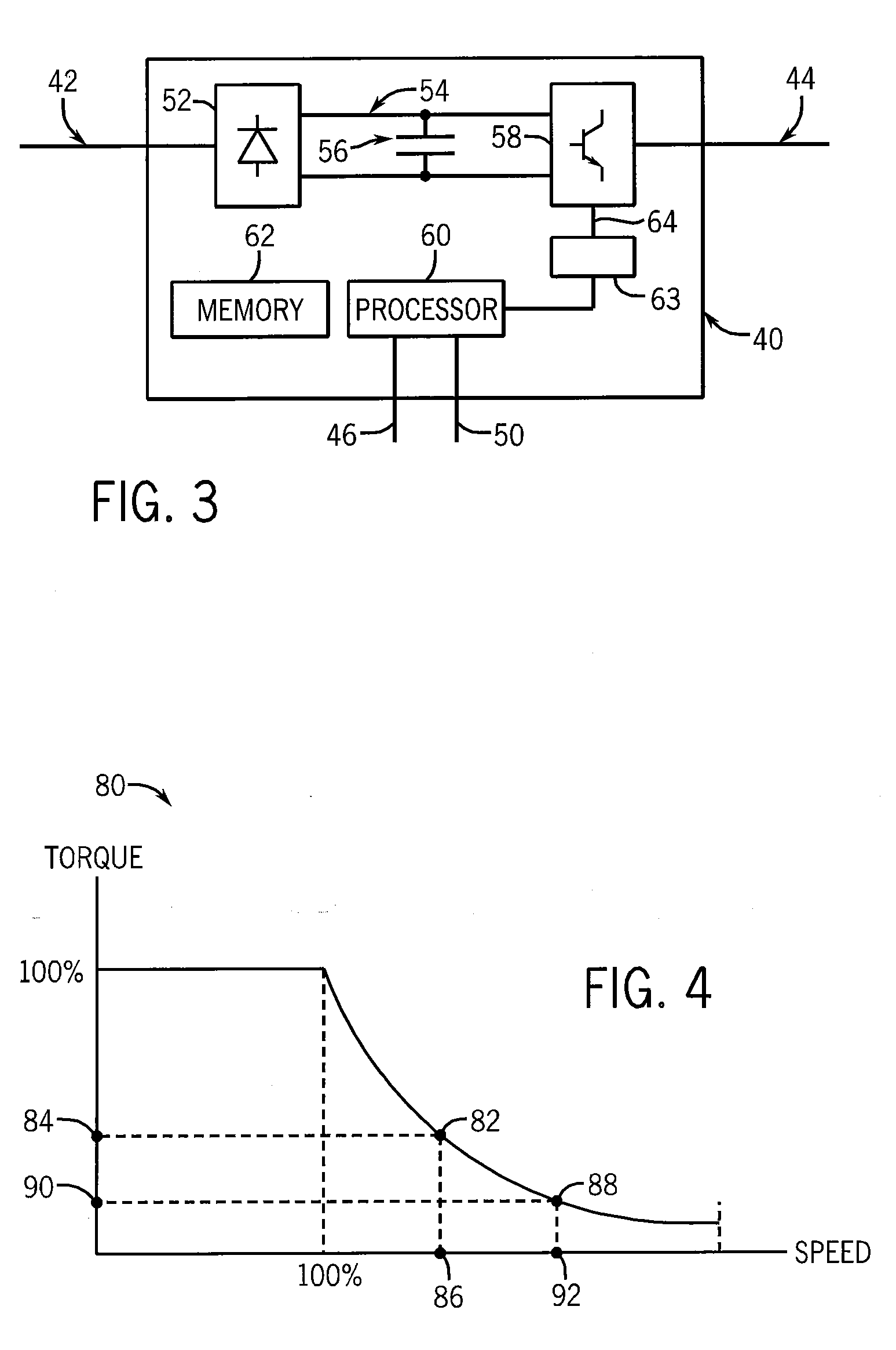
[0016]As another aspect of the invention, the method may also retrieve a torque-speed profile prior to determining the maximum rotational speed, and the maximum rotational speed may also be a function of the torque-speed profile. Initially, a torque-speed profile for the motor may be stored in the motor drive, and the maximum rotational speed may be selected at a speed less than the speed indicated by the torque-speed profile.
[0017]As still another aspect of the invention, a speed feedback signal is received at the motor drive, which corresponds to the rotational speed of the motor. At a periodic interval, the speed feedback signal is compared to a predetermined threshold stored in the motor drive. The predetermined threshold is a function of the maximum rotational speed, and if the speed feedback signal is greater than the predetermined threshold, the motor drive indicates a fault condition, stopping rotation of the motor. However, if the speed feedback signal is less than the predetermined threshold, the motor drive continues to rotate the motor.

Problems solved by technology

As a result, the efficiency of the material handling system impacts the efficiency of the manufacturing process.
If the load decreases during operation, the motor no longer operates at peak efficiency, and if the load increases during operation, the motor may not be able to produce sufficient torque at the current speed to maintain control of the load.

Method used


Image

  • Method and Apparatus for Load Dependent Speed Control of a Motor
  • Method and Apparatus for Load Dependent Speed Control of a Motor
  • Method and Apparatus for Load Dependent Speed Control of a Motor

Examples


Embodiment Construction

[0026]The various features and advantageous details of the subject matter disclosed herein are explained more fully with reference to the non-limiting embodiments described in detail in the following description.

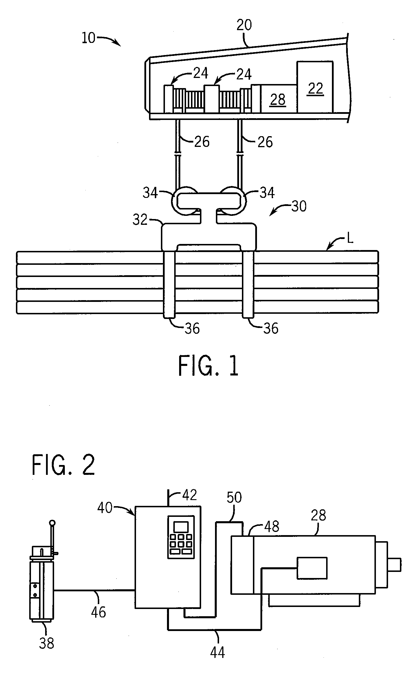
[0027]Turning initially to FIG. 1, a grapple crane 10 includes a boom 20 from which the grapple 30 is suspended. The grapple 30 is suspended by a cable 26 which is secured to, and wound around, one or more drums 24. As illustrated, the cable 26 passes through two pulleys 34 mounted on an upper portion of a frame 32 of the grapple 30. The jaws 36 are pivotally mounted to a lower portion of the frame 32 and may be selectively opened or closed to release or grab a load, L, respectively. As is known in the art, many configurations of grapples 30 exist with, for example, varying frames 32, numbers of pulleys 34, or numbers and styles of jaws 36.

[0028]As illustrated, the drums 24 are rigidly mounted to the boom 20. Optionally, the drums 24 may be mounted remotely from the boom, fo...


PUM


Abstract

A variable speed power converter controls the speed of a load in a material handling system as a function of the torque required to move the load. While the power converter is running, the torque being produced in the motor is determined. The power converter then determines the maximum rotational speed of the motor as a function of the torque currently being produced and of the torque-speed curve of the motor. The power converter then commands the motor to rotate at this maximum rotational speed. The power converter periodically monitors the torque being produced and adjusts the maximum rotational speed of the motor throughout the run.

Description

BACKGROUND OF THE INVENTION[0001]The subject matter disclosed herein relates to variable speed control of a motor. More specifically, the subject matter disclosed herein relates to a method and apparatus for controlling the speed of a motor used in a material handling system as a function of the load applied to the motor.[0002]Material handling systems are widely used to lift heavy loads, weighing up to hundreds of tons. A typical material handling system includes at least one motor used to raise and lower the load and at least one additional motor to position the material handling system over the load to be moved. Common applications include manufacturing facilities, in which large components may be positioned for assembly and / or the final assembly may be moved for shipping. In the shipping industry, containers are loaded and unloaded between storage facilities, trucks, trains, and ships. Such material handling systems typically include a hook block, connected by a cable to a drum,...

Claims


Application Information

Patent Timeline
Patent Type & Authority Applications(United States)
IPC IPC(8): H02P7/06
CPCH02P7/06
Inventor KURECK, AARON S.VERHEYEN, KURTIS L.
Owner MAGNETEK
Learn More