Method for developing multilayer imageable elements

a multi-layer, image-forming technology, applied in the field of lithographic printing, can solve the problems of inconsistent tone images, unacceptable variations in dot percentages throughout the developer loading cycle, and liable to fatten halftone dots with plates

Inactive Publication Date: 2005-07-28
KODAK POLYCHROME GRAPHICS
View PDF18 Cites 104 Cited by
  • Summary
  • Abstract
  • Description
  • Claims
  • Application Information

AI Technical Summary

Problems solved by technology

Although conventional developers and methods of processing work well with imaged thermally imageable multi-layer elements that have been imaged using conventional halftone screening, unacceptable variations in dot percentages are observed throughout the developer loading cycle when the imageable elements have been imaged using stochastic screening.
The resultant tone images are inconsistent and the halftone dots are liable to fatten with plates processed later in the developer loading cycle.

Method used


Image

  • Method for developing multilayer imageable elements
  • Method for developing multilayer imageable elements
  • Method for developing multilayer imageable elements

Examples


example 1

[0080] SWORD® Excel printing plate precursors were imaged with 830 nm radiation using an internal test pattern on a CREO® 3230 Trendsetter (120 mJ / cm2, 250 rpm, 13.25 W laser power). The internal test pattern contained 0, 2, 5,10, 20, 30, 40, 50, 60, 70, 80, 90, 95, 98 and 100% dot images. Imaging was carried out using CREO® Staccato (FM) 10 micron and 20 micron screen ruling at about 94.5 lines per cm (200 line pairs per inch) and a test pattern using the more familiar about 113.4 lines per cm (240 line pairs per inch), round dot AM screen rulings.

[0081] A Unigraph Compact Microtec 60 desktop plate processor (Unigraph Equipment, Thetford, UK) was modified such that developer could be pumped from a container, through a pump (Model AC-56-Md, March Manufacturing, Glenview, Ill., USA) and valve, into a spray bar (8 holes, about 25.4 mm (1 inch) apart). Low levels of developer can be dribbled onto the incoming imageable element. The developer spreads over the surface of the imageable e...

example 2

[0091] Example 1 was repeated, except that (1) SWORD® Ultra printing plate precursors were used and (2) the precursors were imaged with 830 nm radiation using an internal test pattern on the CREO® 3230 Trendsetter at 105 mJ / cm2 (250 power).

[0092] The imaged imageable elements were processed using Goldstar™ developer in the processor described above. The results are shown in Table 2.

TABLE 210 Micron Staccato Screen20 Micron Staccato Screen240 lpi, round dot AM Screen0.58 m20.58 m20.58 m2 of0.58 m2of plate0.58 m2of plateplateof plateprocessedof plateprocessed0.58 m2processedTheoreticalprocessed2 weeksDotprocessed2 weeksDotof plate2 weeksDotDoton day 1laterdifferenceon day 1laterdifferenceprocessedlaterdifference(%)Measured Dot (%)Measured Dot (%)Measured Dot (%)00000000002231121231545145155010101221011110100202221121221192013032311323202930140434304242039412505353052520505116063630626316051170737217273170711808382182820808119092920919219091195979619696094951989999098980979811001001...

example 3

[0093] SWORD® Excel printing plate precursors were imaged with 830 nm radiation using an internal test pattern on a CREO® 3230 Trendsetter (120 mJ / cm2, 230 rpm, 11.5 W laser power). The internal test pattern contained 0, 2, 5, 10, 25, 35, 40, 50, 60, 70, 80, 90, 95, 98 and 100 % dot images. The imagewise exposure was carried out using a CREO® Staccato (FM) 10 micron and 20 micron screen ruling at about 94.5 lines per cm (200 line pairs per inch) and a test pattern using the more familiar about 113.4 lines per cm (240 line pairs per inch), round dot AM screen rulings.

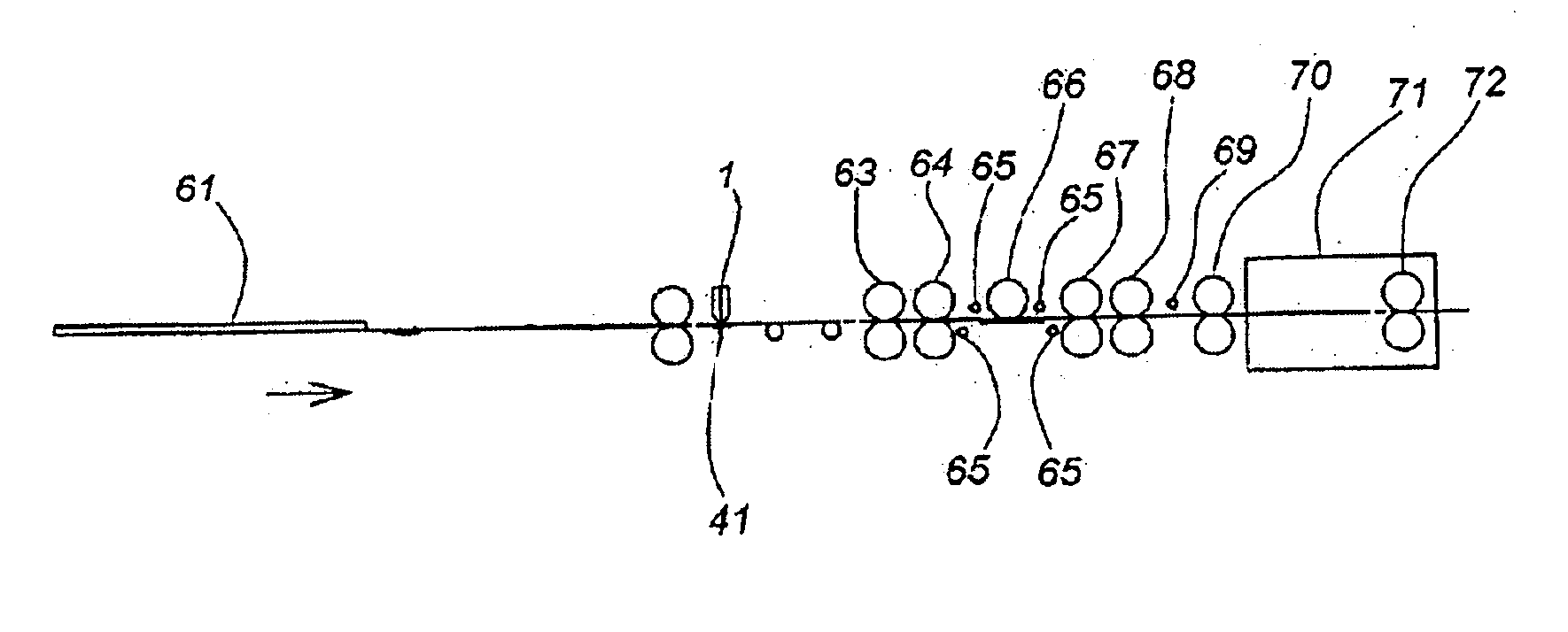
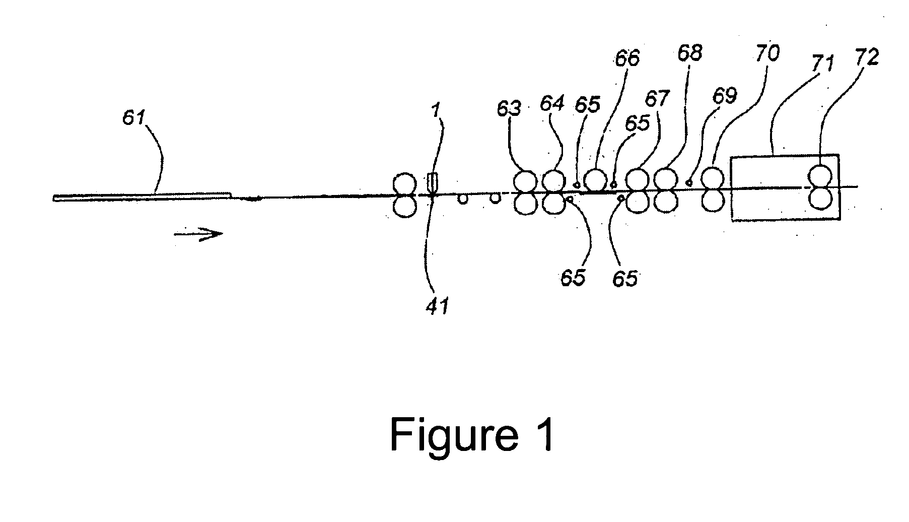
[0094] The imaged imageable elements were developed using 956 developer in an apparatus similar depicted in FIG. 1. A Unigraph Compact Microtec 60 desktop plate processor (Unigraph Equipment Ltd, Thetford, UK) was modified such that developer could be pumped from a container, through a pump (model AC-56-Md, March Manufacturing Inc., Glenview, Ill.) and valve, into a slot coater 1. Developer was applied to the complete f...


PUM

PropertyMeasurementUnit
temperatureaaaaaaaaaa
weight ratioaaaaaaaaaa

Abstract

A method for forming an image by imaging and developing a multi-layer imageable element, in which the developer is fresh developer and the developer is not reused, is disclosed. Much smaller variation in dot percentage is obtained when each imaged imageable element is developed in fresh developer than when the developer is reused to develop additional imaged imageable elements. The method is especially suited to the formation of images using stochastic screening. Either a solvent based developer or a high pH developer may be used.

Description

FIELD OF THE INVENTION [0001] The invention relates to lithographic printing. In particular, this invention relates to a method for forming an image using multi-layer, positive-working, thermally imageable elements that are useful as lithographic printing plate precursors. BACKGROUND OF THE INVENTION [0002] In conventional or “wet” lithographic printing, ink receptive regions, known as image areas, are generated on a hydrophilic surface. When the surface is moistened with water and ink is applied, the hydrophilic regions retain the water and repel the ink, and the ink receptive regions accept the ink and repel the water. The ink is transferred to the surface of a material upon which the image is to be reproduced. Typically, the ink is first transferred to an intermediate blanket, which in turn transfers the ink to the surface of the material upon which the image is to be reproduced. [0003] Imageable elements useful as lithographic printing plate precursors typically comprise an imag...

Claims


Application Information

Patent Timeline
Patent Type & Authority Applications(United States)
IPC IPC(8): B41C1/10B41J2/335B41M5/36
CPCB41C1/1016B41C2210/02B41C2210/06B41C2210/262B41C2210/22B41C2210/24B41C2210/14
Inventor SHIMAZU, KEN-ICHIRAY, KEVIN B.
Owner KODAK POLYCHROME GRAPHICS
Why Eureka
Try Eureka