Temperature information reader

a technology of temperature information and reader, which is applied in the direction of instruments, heat measurement, electric signalling details, etc., can solve the problems of troublesome operations, deterioration of accuracy, and long time-consuming measuremen

Inactive Publication Date: 2005-07-28
SANYO ELECTRIC CO LTD
View PDF16 Cites 7 Cited by
  • Summary
  • Abstract
  • Description
  • Claims
  • Application Information

AI Technical Summary

Benefits of technology

[0012] The preferred embodiments of the present invention have been developed in view of the above-mentioned and/or other problems in

Problems solved by technology

Typically, there were, among other problems, the following drawbacks in measuring patient's body temperatures in hospitals.
In the case of using mercury thermometers, it takes a long time to complete the measurement.
Otherwise, the accuracy deteriorates.
Therefore, a nurse is required to complete the recoding operation in addition to the b

Method used


Image

  • Temperature information reader
  • Temperature information reader
  • Temperature information reader

Examples


Embodiment Construction

[0061] In the following paragraphs, some preferred embodiments of the invention will be described by way of example and not limitation. It should be understood based on this disclosure that various other modifications can be made by those in the art based on these illustrated embodiments.

[0062] A preferable embodiment of the present invention will be explained with reference to the attached drawings. The following explanation will be directed to a temperature information reader to be used in combination with an adhesive clinical thermometer pad for measuring body temperatures of patients in hospitals. However, it should be understood that the present invention is not limited to the above and can also be applied to various applications required to measure a surface temperature of an object in various industries.

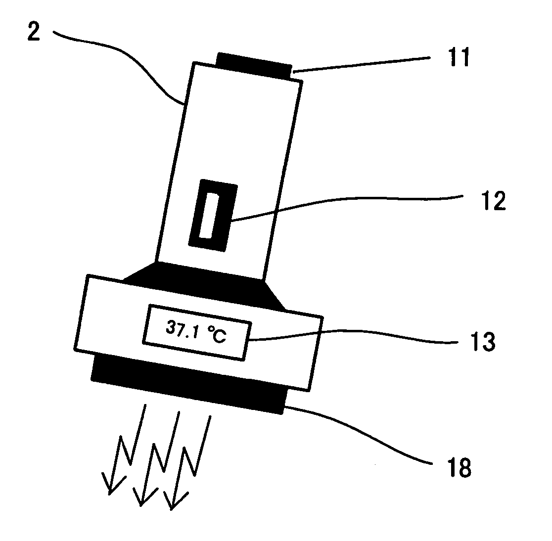
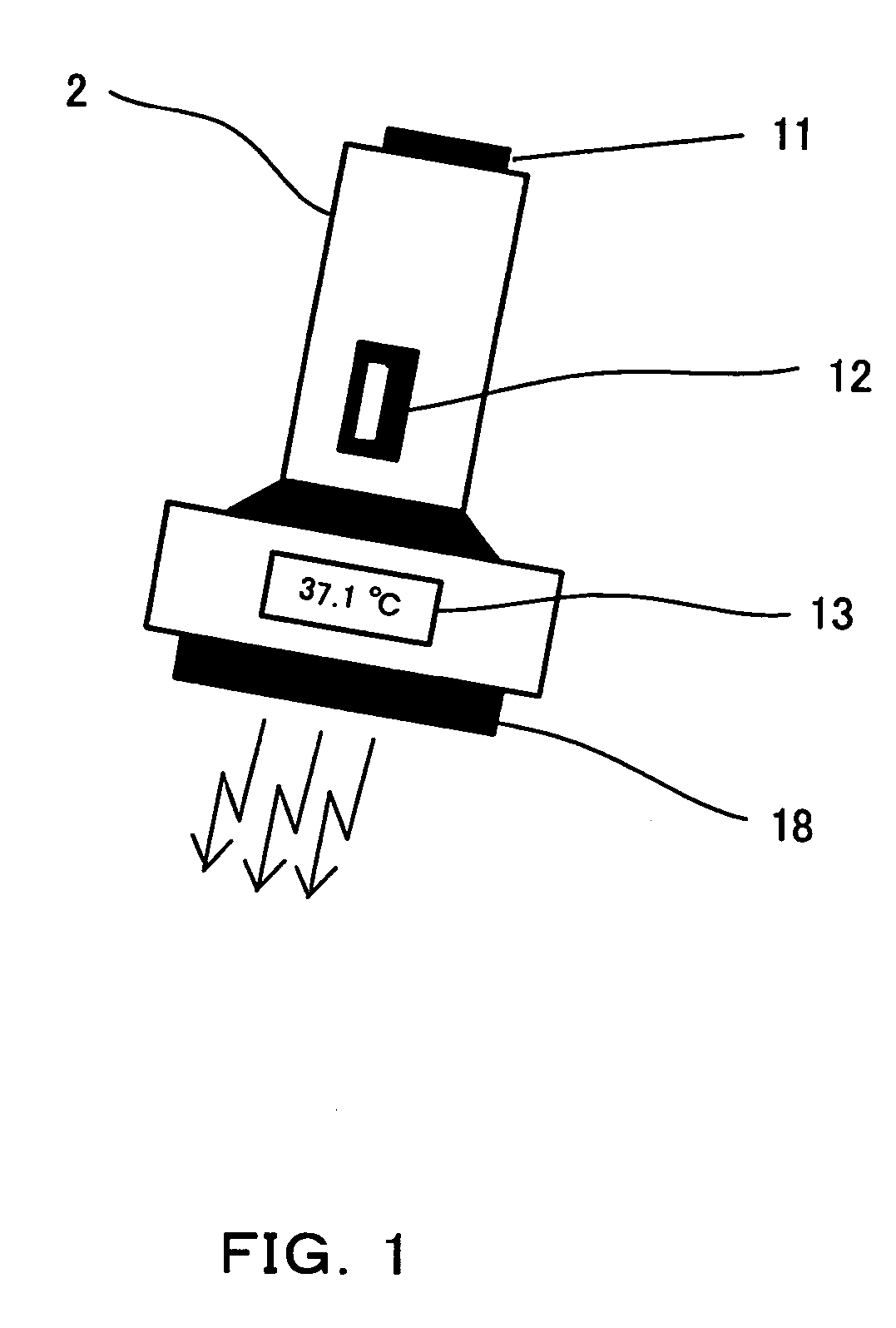
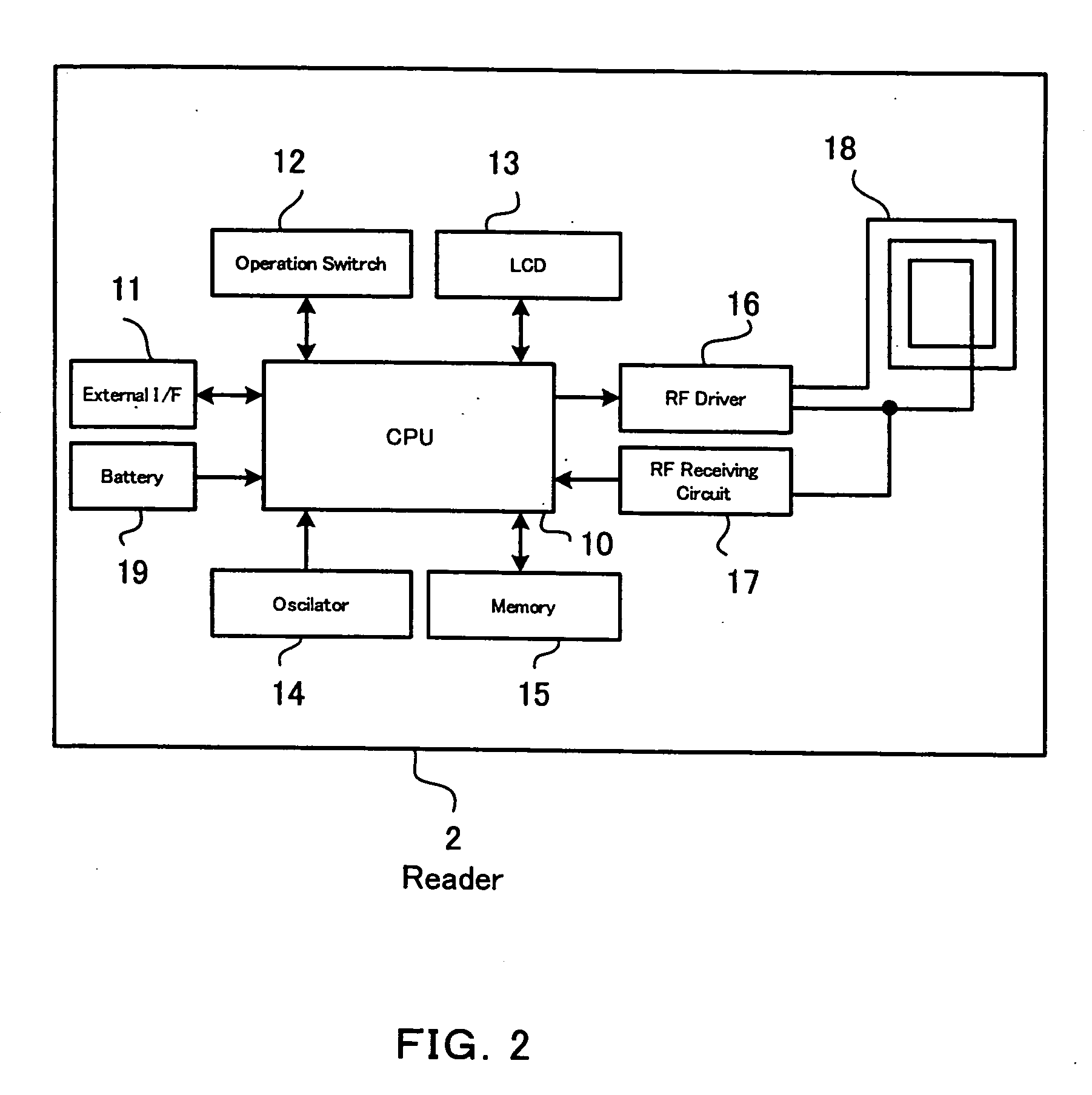
[0063]FIG. 1 is a schematic view showing a temperature information reader 2 according to an embodiment of the present invention. This reader 2 is preferably used in combinat...


PUM


Abstract

In some embodiments, a temperature information reader is used in combination with a temperature measuring pad to be attached to a surface of an object for measuring a temperature of the object. In some examples, the temperature measuring pad receives a radio wave, generates electric power from the received radio wave, measures the temperature of the object, and wirelessly outputs temperature information including the measured temperature and an ID code give to the temperature measuring pad toward the temperature information reader. The temperature information reader includes, e.g., an antenna portion for transmitting the radio wave toward the temperature measuring pad and receiving the temperature information from the temperature measuring pad, a radio wave generating portion for generating the radio wave to be transmitted toward the temperature measuring pad via the antenna portion, a receiving portion for wirelessly receiving the temperature information from the temperature measuring pad via the antenna portion, a storing portion for storing the temperature information, a display portion for displaying at least the measured body temperature, and an external interface for transferring the temperature information stored in the storing portion to an external device.

Description

CROSS REFERENCE TO RELATED APPLICATIONS [0001] This is continuation-in-part of commonly assigned co-pending PCT application No. PCT / JP03 / 03437, filed on Mar. 20, 2003, designating the United States of America as one of designation countries and claiming the benefit of the filing date of Japanese Patent Application No. 2002-78049 filed on Mar. 20, 2002, the entire disclosures of which are incorporated herein by reference in their entireties.[0002] This application claims priority under 35 U.S.C.§119 to Japanese Patent Application No. P2003-338863 filed on Sep. 29, 2003, the entire disclosure of which is incorporated herein by reference in its entirety. BACKGROUND OF THE INVENTION [0003] 1. Field of the Invention [0004] The present invention relates to, inter alia, an adhesive clinical thermometer pad and a temperature measuring pad to be used in connection with a reader for reading temperature information of a patient from the thermometer pad. [0005] 2. Description of the Related Art...

Claims


Application Information

Patent Timeline
IPC IPC(8): G01K1/02G01K13/00
CPCG01K13/002G01K1/02G01K13/20
Inventor NAKAZAWA, TSUTOMUSAKANO, MOTOYA
Owner SANYO ELECTRIC CO LTD
Why Eureka
Try Eureka