Dual line protractor for biometric measurements

a biometric measurement and protractor technology, applied in the field of goniometers, can solve the problems of inconvenient use, inconvenient use, and inability to measure the motion of the limb intended to be measured, and achieve the effects of convenient use, high precision and accuracy, and simple dual line protractor

Inactive Publication Date: 2008-07-29
PARKER EMMETT L
View PDF23 Cites 2 Cited by
  • Summary
  • Abstract
  • Description
  • Claims
  • Application Information

AI Technical Summary

Benefits of technology

[0008]An advantage of the present invention is a simple dual line protractor that measures body joint angles with excellent precision and accuracy.
[0009]Another advantage is a dual line protractor that measures body joint angles quickly and easily.
[0010]Another advantage is a dual line protractor that can measure the extent of joint rotation of most body joints.
[0011]Another advantage is a dual line protractor that can measure any joint angle as the relative positions of two body members sharing the same joint move with respect to each other.
[0012]Another advantage is the ability to measure dynamic joint angles in addition to static joint angles.
[0013]Another advantage is that the tip of the line can be attached directly to a specific anatomical landmark on a body member, producing remarkable accuracy and precision in the measurement of angles between the anatomical landmarks and between the body members.

Problems solved by technology

These devices were cumbersome, unreliable, and difficult to mount.
They could interfere with the motion of the limb they were intended to measure and were not particularly useful.
More recent devices using electronic means of measuring angular relationships suffer from similar problems.
These electronic devices are complex, expensive, and can suffer from lack of accuracy and precision due to variations in the direction of the energy beam or consistent detection of an energy beam.
However, they have not been adaptable as goniometers to measure angles of body members.

Method used


Image

  • Dual line protractor for biometric measurements
  • Dual line protractor for biometric measurements
  • Dual line protractor for biometric measurements

Examples


Embodiment Construction

[0018]While the following description details the preferred embodiments of the present invention, it is to be understood that invention is not limited in its application to the details of construction and arrangement of the parts illustrated in the accompanying drawings, since the invention is capable of other embodiments and of being practiced in various ways.

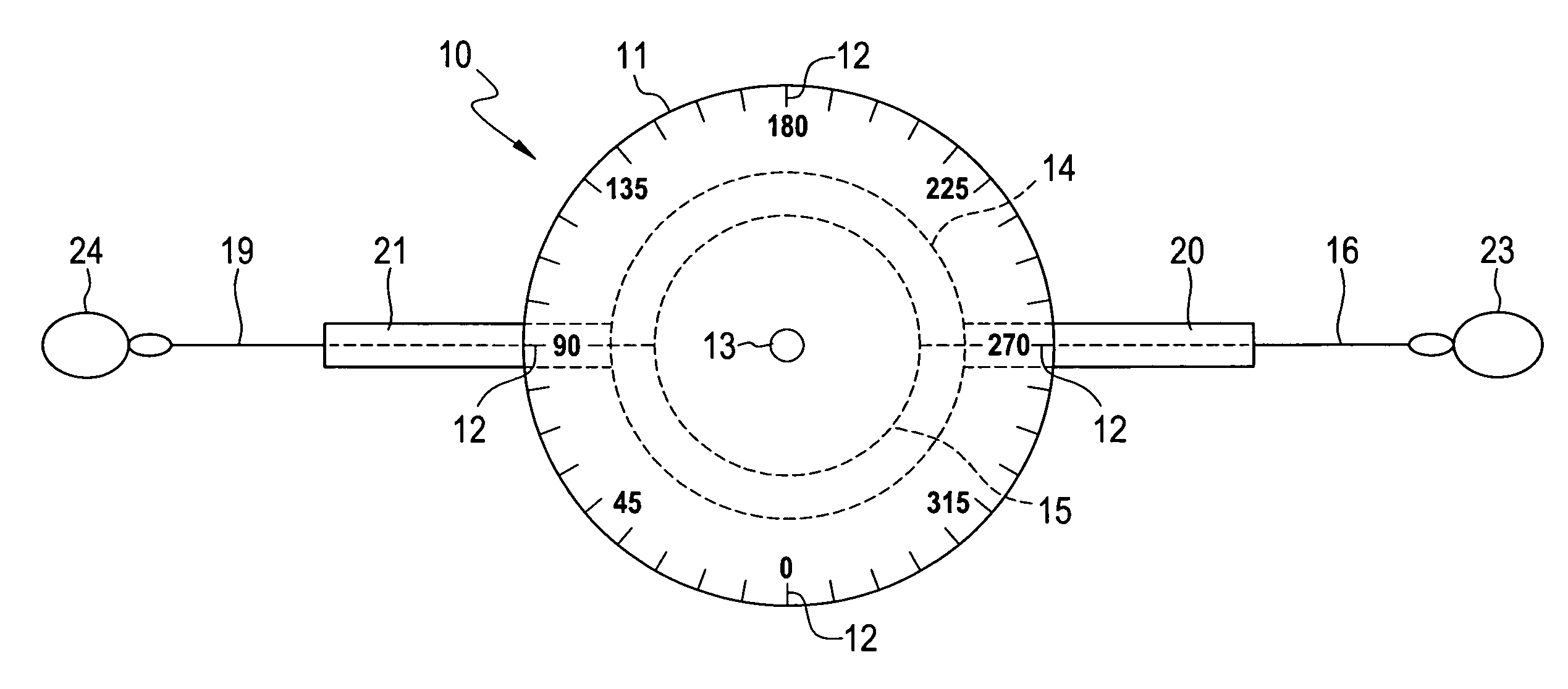
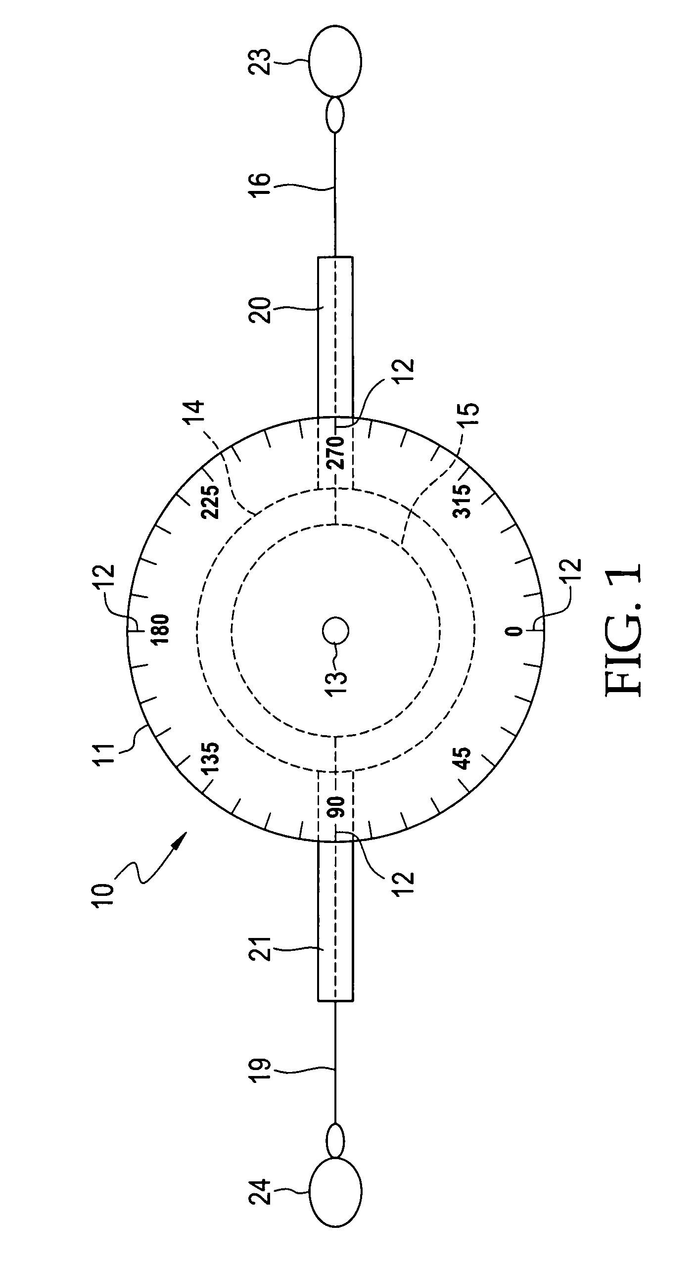
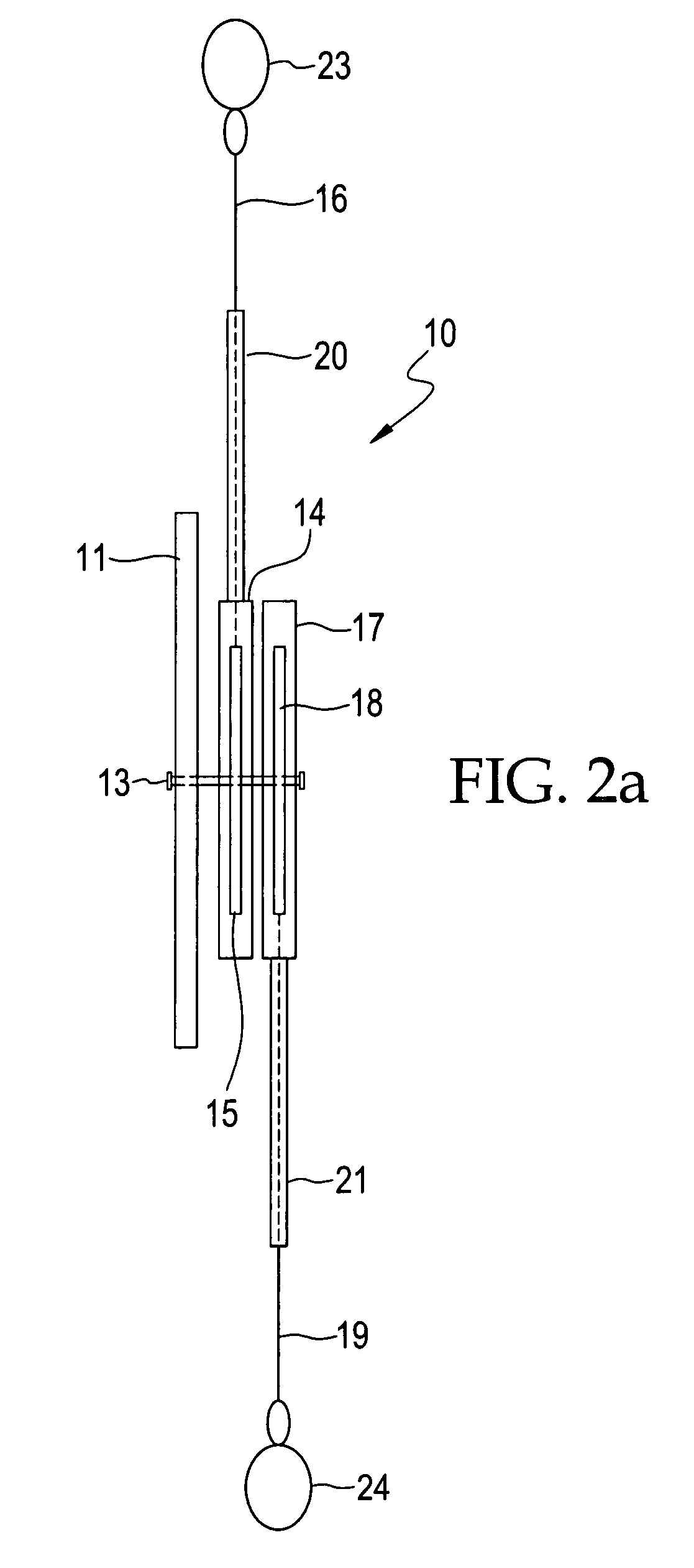
[0019]FIG. 1 shows a front view of the dual line protractor 10 of the present invention. The protractor 11 has degree marks 12 typical of protractors known in the art. The protractor 11 is, preferably, a 360 degree protractor. Protractor 11 is fixed to a central axis 13. Behind protractor 11 is a first circular housing 14 which is attached rotatably to the central axis 13. A first spool 15 is inside first housing 14 and first spool 15 is also attached rotatably to the central axis 13. A first line 16 is wound around first spool 15. First spool 15 is biased to retract or rewind first line 16 onto first spool 15, by mechanisms w...


PUM


Abstract

A dual line protractor fixed to a central axis which has two housings, each housing having a spool with retractable lines, the housings and spools being rotatably attached to the central axis. The spools and housings rotate independently of each other on the central axis. The lines can be extended from the spools and the tips of the lines are attached to anatomical landmarks on first and second body members. The protractor is placed on a joint between the first and second body members. The lines extend from the spools and housings over degree marks on the protractor. The difference between the degree marks provide the angle between the body members at the joint. The application of the dual line protractor for these measurements is simple and rapid, requiring only a few minutes, so that the range of motion of several joints with several repeat measurements can be performed in a relatively short period of time. Placing the tips of the lines on anatomical landmarks produces remarkable accuracy and precision in the measurement of joint angles. Because string-like lines are used to indicate the degree marks, the dual line protractor does not interfere with the natural motion of the body member being measured, allowing accurate dynamic joint angle measurement.

Description

REFERENCE TO RELATED PATENT APPLICATION[0001]The present patent application is a divisional of U.S. patent application Ser. No. 11 / 244,309, filed on Oct. 5, 2005, now U.S. Pat. No. 7,293,363, the disclosure of which is incorporated herein by reference.BACKGROUND OF THE INVENTION[0002]1. Field of the Invention[0003]The present invention relates to goniometers for measuring angles between body members and, more particularly, to a dual line protractor to measure the angle between two body members at a joint between the members at any desired orientation between the members.[0004]2. Technical Background[0005]The range of motion of a body joint is commonly measured to determine the presence and extent of joint abnormalities or the degree of healing and recovery from joint injuries. After a joint related injury a patient is often directed to limit the range of motion of a joint. Success of physical therapy and recovery is typically evaluated by improved ranges of motion of the injured joi...

Claims


Application Information

Patent Timeline
Patent Type & Authority Patents(United States)
IPC IPC(8): B43L7/10
CPCA61B5/1071G01B3/563A61B5/4528
Inventor PARKER, EMMETT L.
Owner PARKER EMMETT L
Why Eureka
Try Eureka