

Method and apparatus for steering movable object by using control algorithm that takes into account the difference between the nominal and optimum positions of navigation antenna
a technology of steering control algorithm and movable object, which is applied in the direction of navigation instruments, underwater vessels, non-deflectable wheel steering, etc., can solve the problems of undesired weaving, performance degradation of automatic steering control algorithm, and mounting of navigation antennas
Active Publication Date: 2005-07-28
TRIMBLE NAVIGATION LTD
View PDF15 Cites 32 Cited by
- Summary
- Abstract
- Description
- Claims
- Application Information
AI Technical Summary
Benefits of technology
[0032] Yet, one more aspect of the present invention is directed to an apparatus for steering a vehicle along a predetermined 2-D path on a 2-D plane. In one embodiment of the present invention, the apparatus for steering a vehicle along a predetermined 2-D path on a 2-D plane comprises: (A) a means for obtaining a set of positioning data of the vehicle; (B) a means for modifying the set of positioning data of the vehicle; (C) a means for measuring a steering angle of the front wheels of the vehicle relative to a predetermined reference direction on the 2-D plane; (D) a means for calculating a correction to the measured steering angle on the 2-D plane; and (E) a means for performing a steering action by using the correction to the measured steering angle on the 2-D plane in order to move the vehicle along the predetermined 2-D path on the 2-D plane. In one embodiment of the present invention, the (A) means for obtaining the set of positioning data of the vehicle further includes: (A1) a navigation system selected from the group consisting of: {GPS; GLONASS; combined GPS / GLONASS; GALILEO; pseudolite-based navigation system; and inertial navigation system (INS)}; and (A2) a navigation antenna mounted on the vehicle at an optimum antenna position. In one embodiment of the present invention, the means (C) for measuring the steering angle of the front wheels of the vehicle relative to the predetermined reference direction on the 2-D plane further includes an angular sensor (or a rotary potentiometer) configured to measure the steering angle of the front wheels of the vehicle relative to the predetermined reference direction on the 2-D plane. In one embodiment of the present invention, the means (D) for calculating the correction to the measured steering angle on the 2-D plane further includes (D1) a steering control algorithm configured to use a set of control data to calculate the correction to the measured steering angle on the 2-D plane, wherein the set of control data is selected from the group consisting of: {the set of modified positioning data of the vehicle; the measured steering angle on the 2-D plane; and a set of data defining the predetermined 2-D path on the 2-D plane}. In one embodiment of the present invention, the means (E) for performing the steering action by using the correction to the measured steering angle on the 2-D plane further includes: (E1) a 2-D hydraulic system configured to realize the correction to the measured steering angle on the 2-D plane; or (E2) a 2-D “flight by wire” system configured to realize the correction to the measured steering angle on the 2-D plane.
[0033] Yet, one additional aspect of the present invention is directed to an apparatus for steering a vehicle along a predetermined 3-D path on a 3-D surface. In one embodiment of the present invention, the apparatus for steering a vehicle along a predetermined 3-D path on a 3-D surface comprises: (A) a means for obtaining a set of positioning data of the vehicle; (B) a means for modifying the set of positioning data of the vehicle; (C) a 3-D means for measuring a set of steering angles of the front wheels of the vehicle relative to a predetermined reference direction on the 3-D surface; (D) a means for calculating a set of corrections to the set of measured steering angles on the 3-D surface; and (E) a means for performing a steering action by using the set of corrections to the set of measured steering angles on the 3-D surface in order to move the vehicle along the predetermined 3-D path on the 3-D surface. In one embodiment of the present invention, the (A) means for obtaining the set of positioning data of the vehicle further includes: (A1) a navigation system selected from the group consisting of: {GPS; GLONASS; combined GPS / GLONASS; GALILEO; pseudolite-based navigation system; and inertial navigation system (INS)}; and (A2) a navigation antenna mounted on the vehicle at an optimum antenna position. In one embodiment of the present invention, the means (B) for modifying the set of positioning data of the vehicle further includes a means for specifying a distance between the nominal navigation antenna position and the optimum navigation antenna position. In one embodiment of the present invention, the 3-D means (C) for measuring the set of steering angles of the front wheels of the vehicle relative to the predetermined reference direction on the 3-D surface further includes an angular sensor (or a rotary potentiometer) configured to measure the set of steering angles of the front wheels of the vehicle relative to the predetermined reference direction on the 3-D surface. In one embodiment of the present invention, the means (D) for calculating the set of corrections to the set of measured steering angles on the 3-D surface further includes (D1) a steering control algorithm configured to use a set of control data to calculate the set of corrections to the set of measured steering angles on the 3-D surface; wherein the set of control data is selected from the group consisting of: {the set of modified positioning data of the vehicle; the measured steering angle on the 3-D surface; and a set of data defining the predetermined 2-D path on the 3-D surface}. In one embodiment of the present invention, the means (E) for performing the steering action by using the set of corrections to the set of measured steering angles on the 3-D surface further includes: (E1) a 3-D hydraulic system configured to realize the set of corrections to the set of measured steering angles on the 3-D surface; or (E2) a 3-D “flight by wire” system configured to realize the set of corrections to the set of measured steering angles on the 3-D surface.
Problems solved by technology
Moving the navigation antenna to a different location on the vehicle would result in the performance degradation of the automatic steering control algorithm, in the undesired weaving, or even in instability.
On the other hand, the variety of factors may prevent mounting the navigation antenna at the prescribed nominal location of the vehicle.
Thus, in many prior art cases, the actual navigation antenna location on the vehicle may be different from the nominal assumed navigation antenna location on the vehicle, which can significantly degrade the performance of the prior art automatic steering control algorithm.
Method used
View moreImage
Smart ImageViewing Examples

Examples
example
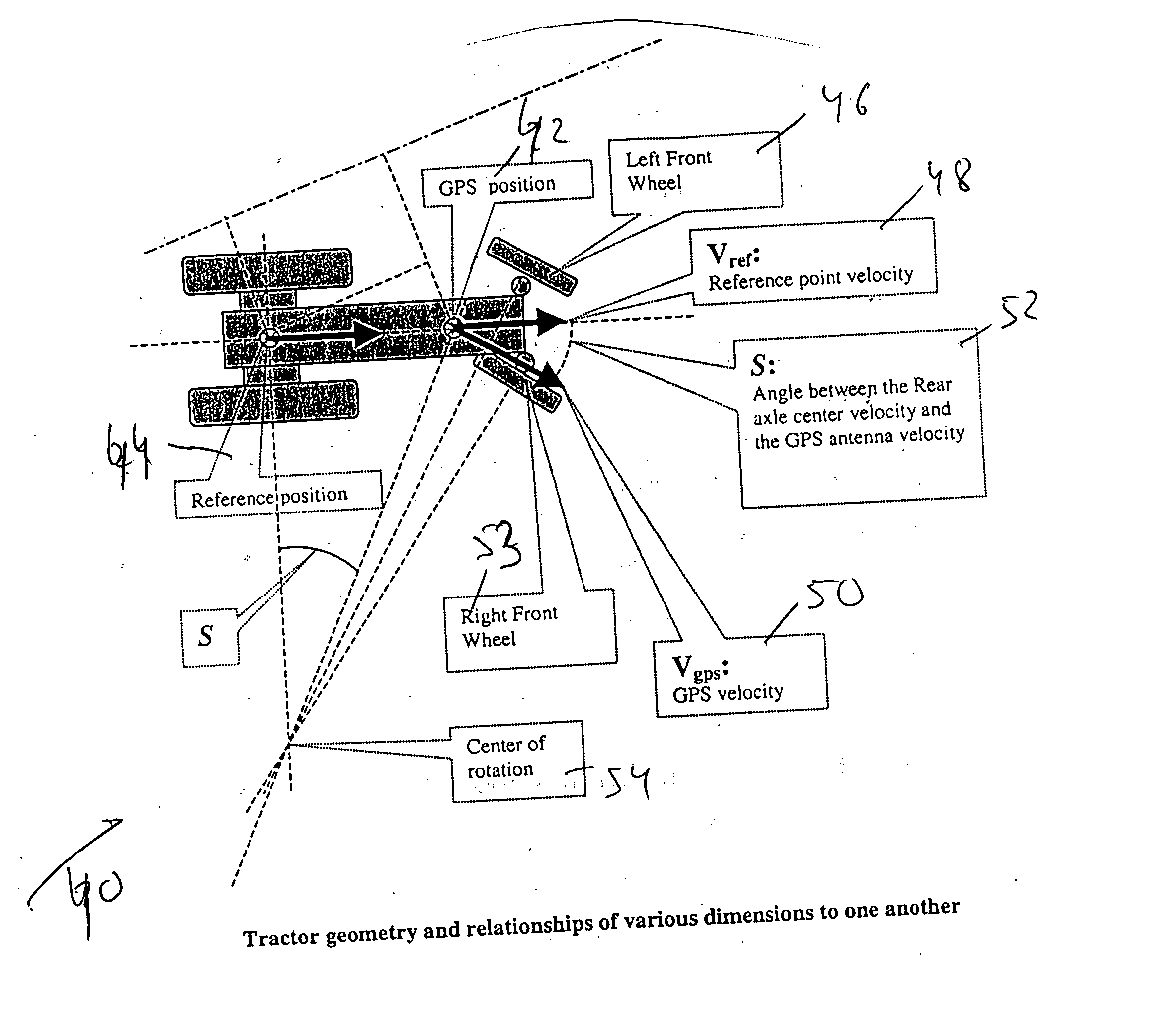
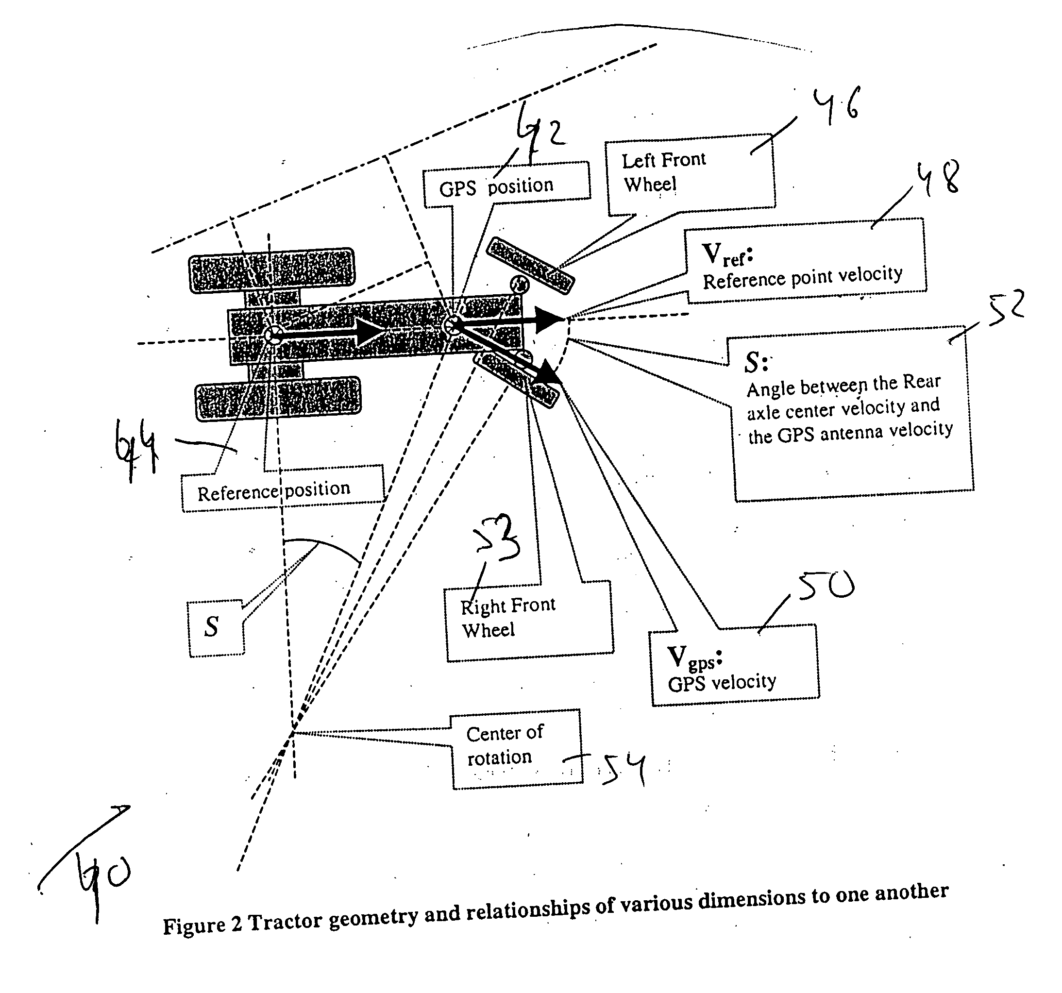
[0076] Translation of the position and speed (velocity) information obtained by the navigation system having the navigation antenna mounted at the optimum location 62 into the speed (velocity) and position at the referenced (expected) nominal location 64 of the navigation (GPS) antenna, as illustrated in FIG. 3:
Login to View More PUM
 Abstract
A method of steering a vehicle along a predetermined, or real time path by using a steering control algorithm. The vehicle includes a navigation system and a navigation antenna. The navigation antenna is mounted on the vehicle at an optimum antenna position, whereas the steering control algorithm assumes a nominal antenna position at a predetermined reference point. The method comprises the following steps: (A) obtaining a set of positioning data of the vehicle by using the navigation system and by using the navigation antenna mounted at the optimum antenna position; (B) modifying the set of positioning data of the vehicle; (C) measuring a steering angle(s) of the front wheels of the vehicle relative to a predetermined reference direction(s); (D) calculating a correction(s) to the measured steering angle(s); and (E) performing a steering action by using the correction(s) to the measured steering angle(s) to move the vehicle along the predetermined, or real time path.
Description
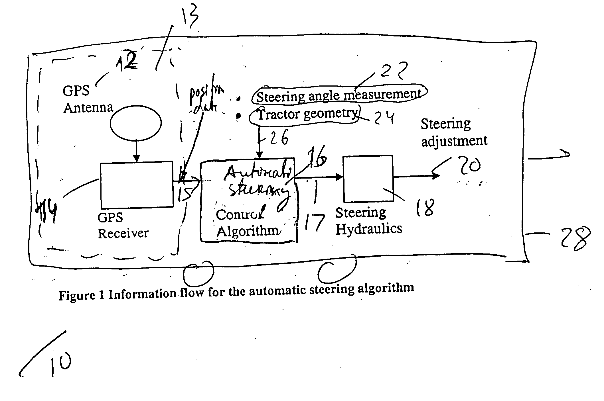
BACKGROUND OF THE INVENTION [0001] 1. Field of the Invention [0002] The present invention is in the field of navigation of vehicles. More specifically, the present invention relates to a method and apparatus for steering vehicles by using a steering control algorithm that takes into account the difference between the nominal and optimum positions of a navigation antenna. [0003] 2. Discussion of the Prior Art [0004] The prior art GPS systems are used to manually or automatically steer a vehicle (like a tractor) along a predetermined path. To achieve an automatic steering, the GPS information is fed to a steering control algorithm which calculates an appropriate steering action to steer the tractor (or another vehicle) onto the prescribed trajectory and keep it on that trajectory. [0005] However, the prior art automatic steering control algorithm is based, among other things, on the assumption that a GPS (or other navigation) antenna is mounted at a specific nominal location on the ve...
Claims
Login to View More Application Information
Patent Timeline
 Patent Type & AuthorityApplications(United States)
IPC IPC(8): A01B59/043E02F3/76G01C21/00G01C21/20G01C22/00G05D1/02G06G7/78H04B7/185
CPCG01C21/20G05D2201/0201G05D1/0278
InventorARAL, GURCAN
OwnerTRIMBLE NAVIGATION LTD