Vehicle yaw rate correction

a technology for determining the yaw rate and vehicles, applied in the field of vehicles, can solve problems such as poor or even failure of vehicle systems, invoking emergency braking of vehicles, and braking being dangerous

Active Publication Date: 2013-09-05
MAGNA ELECTRONICS
View PDF0 Cites 110 Cited by
  • Summary
  • Abstract
  • Description
  • Claims
  • Application Information

AI Technical Summary

Benefits of technology

[0004]A yaw rate offset is used to correct measured yaw rate error. In some embodiments, the yaw rate offset may be updated when the vehicle is stationary. The vehicle may be determined to be stationary by referencing at least two sensors. The first sensor provides an indication that the vehicle speed is zero. In embodiments, wherein the first sensor is a speed sensor, it can be insensitive to movement at low speeds, such as when pulling out of a parking space. Thus, the acceleration or derivative of acceleration (commonly referred to as “jerk”) obtained from the second sensor, which is sensitive to slight movements, is also used to more confidently determine that the vehicle is stationary. In some embodiments, the yaw rate offset may be updated when the vehic

Problems solved by technology

Yaw rate sensors are susceptible to error, and if the measured yaw rate has significant error, then these kinds of vehicle systems may perform poorly or even fail.
For example, significant error in the measured yaw rate could trigger a collision mitigation system to mistakenly determine that the vehicle is going to collide with another vehicle

Method used


Image

  • Vehicle yaw rate correction
  • Vehicle yaw rate correction
  • Vehicle yaw rate correction

Examples


Embodiment Construction

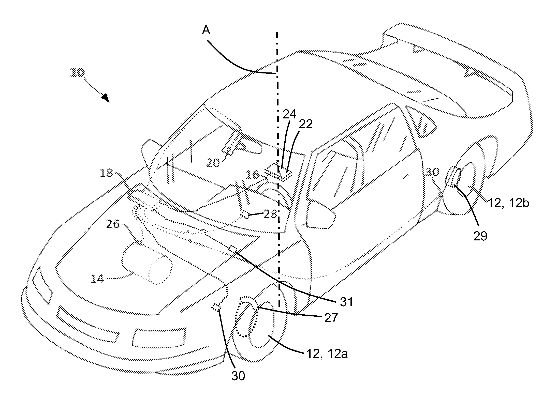
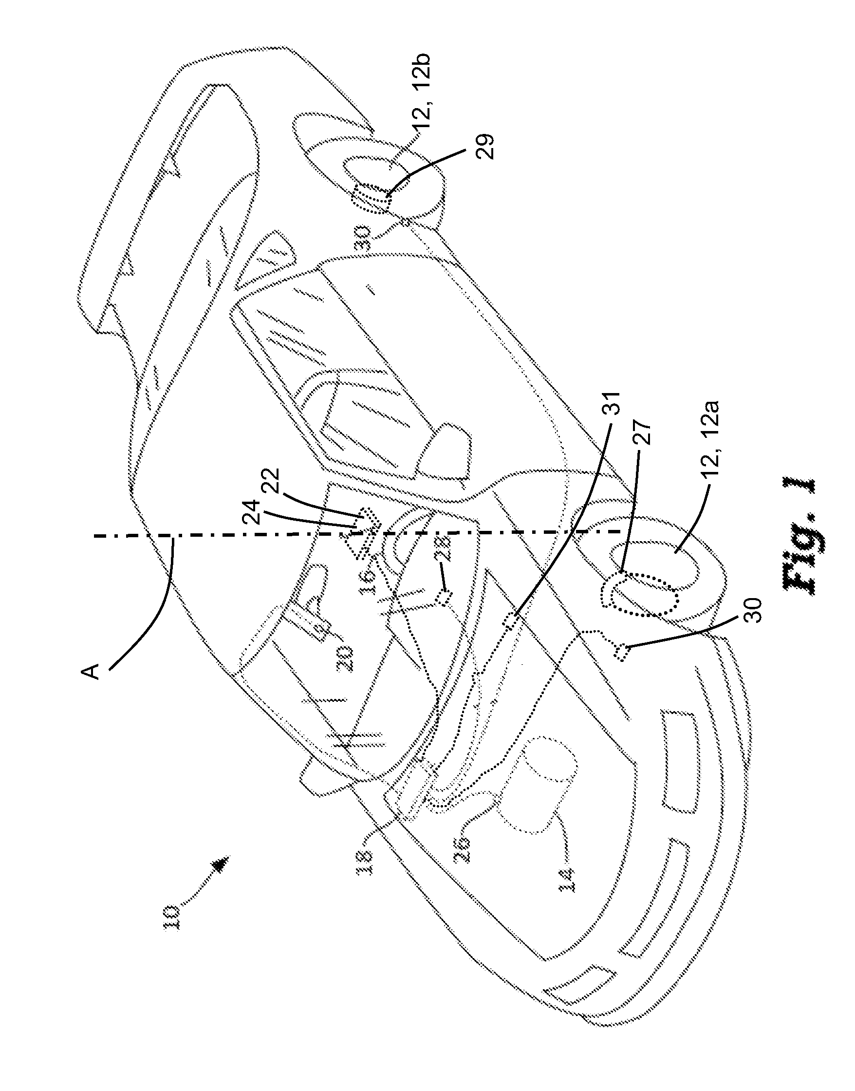
[0035]Referring now to the drawings and the illustrative embodiments depicted therein, FIG. 1 illustrates a land-based vehicle 10 equipped with the system of the present invention. In this example, the vehicle 10 is a passenger car, but in other examples, the vehicle may be a truck, bus, van, motorcycle, or any other kind of vehicle. In the illustrated embodiment, the equipped vehicle 10 includes a body, a passenger area, wheels 12 (including front wheels 12a and rear wheels 12b), an internal combustion engine and / or an electric motor to drive the vehicle 10, a transmission 14 to convey power from the engine or motor to the wheels 12, a steering wheel 16 to turn the front wheels 12a, as well as other components for powering and controlling the vehicle 10. Clearly, the equipped vehicle may have other systems or components, such as, for example, steering of the rear wheels 12b or the like, without affecting the scope of the present invention.

[0036]As shown in FIG. 1, the vehicle 10 fu...


PUM


Abstract

A control system or method for a vehicle references a camera and sensors to determine when an offset of a yaw rate sensor may be updated. The sensors may include a longitudinal accelerometer, a transmission sensor, a vehicle speed sensor, and a steering angle sensor. The offset of the yaw rate sensor may be updated when the vehicle is determined to be stationary by referencing at least a derivative of an acceleration from the longitudinal accelerometer. The offset of the yaw rate sensor may be updated when the vehicle is determined to be moving straight by referencing at least image data captured by the camera. Lane delimiters may be detected in the captured image data and evaluated to determine a level of confidence in the straight movement. When the offset of the yaw rate sensor is to be updated, a ratio of new offset to old offset may be used.

Description

CROSS REFERENCE TO RELATED APPLICATION[0001]The present application claims the filing benefit of U.S. provisional application Ser. No. 61 / 605,516, filed Mar. 1, 2012, which is hereby incorporated herein by reference in its entirety.FIELD OF THE INVENTION[0002]This disclosure relates to vehicles, and more particularly to improving the accuracy of the determination of yaw rate in vehicles.BACKGROUND OF THE INVENTION[0003]Sensing yaw rate is important to land-based vehicles, and specifically, to road-going vehicles. Vehicle systems, such as collision avoidance systems, collision mitigation systems and stability control systems, may require accurate values of yaw rate to correctly determine the projected path of vehicle travel. Yaw rate sensors are susceptible to error, and if the measured yaw rate has significant error, then these kinds of vehicle systems may perform poorly or even fail. For example, significant error in the measured yaw rate could trigger a collision mitigation system...

Claims


Application Information

Patent Timeline
IPC IPC(8): B60W40/114
CPCB60W50/0098H04N5/374B60W2420/42B60W2520/14B60W40/114B60T7/22B60W2520/10G01J5/024G01J5/34G01J2005/0077B60T7/12B60W30/08B60W30/12H04N5/23229B60W2050/0049G06V20/588H04N23/80H04N25/76B60R1/00B60R2300/804G01P3/50G01P13/00G07C5/02G07C5/08H04N7/183
Inventor CHUNDRLIK, JR., WILLIAM J.JOHNSON, NATHANIELWIMMERSHOFF, MARC
Owner MAGNA ELECTRONICS
Why Eureka
Try Eureka