Vacuum sweeper

a vacuum cleaner and sweeping technology, applied in the field of vacuum cleaners, can solve the problems of affecting the back of the user, affecting the use of the vacuum cleaner, so as to achieve the effect of easy and smooth operation

Active Publication Date: 2005-08-04
JANPRO PROD LLC
View PDF5 Cites 6 Cited by
  • Summary
  • Abstract
  • Description
  • Claims
  • Application Information

AI Technical Summary

Benefits of technology

[0023] Preferably, both the long tube and the vacuum head of the invention are formed from a material that is durable and inexpensive. The vacuum head is preferably made of a material that will pass easily and smoothly over different types of floor materials, i.e., wood, linoleum, tile and carpet. The vacuum head is also preferably made to receive selected ground engaging surface members that are particularly useful in vacuuming material from different floor materials.

Problems solved by technology

The repeated bending and standing motion is often damaging to the back of the user.
The entire weight of the vacuum cleaner must be moved during a cleaning operation, the weight being moved contributes to injury to the back of the user.
However, when using the shortened telescopic tube in the manner described, it is slow and tedious to do a large floor since a person must be on hands and knees in order to properly maneuver the vacuum head and to pull the power and suction unit along behind.
The pushing and pulling pattern is necessary to assure that the opening in the vacuum head will pass over a maximum area being vacuumed and, as previously noted may cause significant injury to the back of a user.

Method used


Image

  • Vacuum sweeper
  • Vacuum sweeper
  • Vacuum sweeper

Examples


Embodiment Construction

[0034] Referring now the Drawings

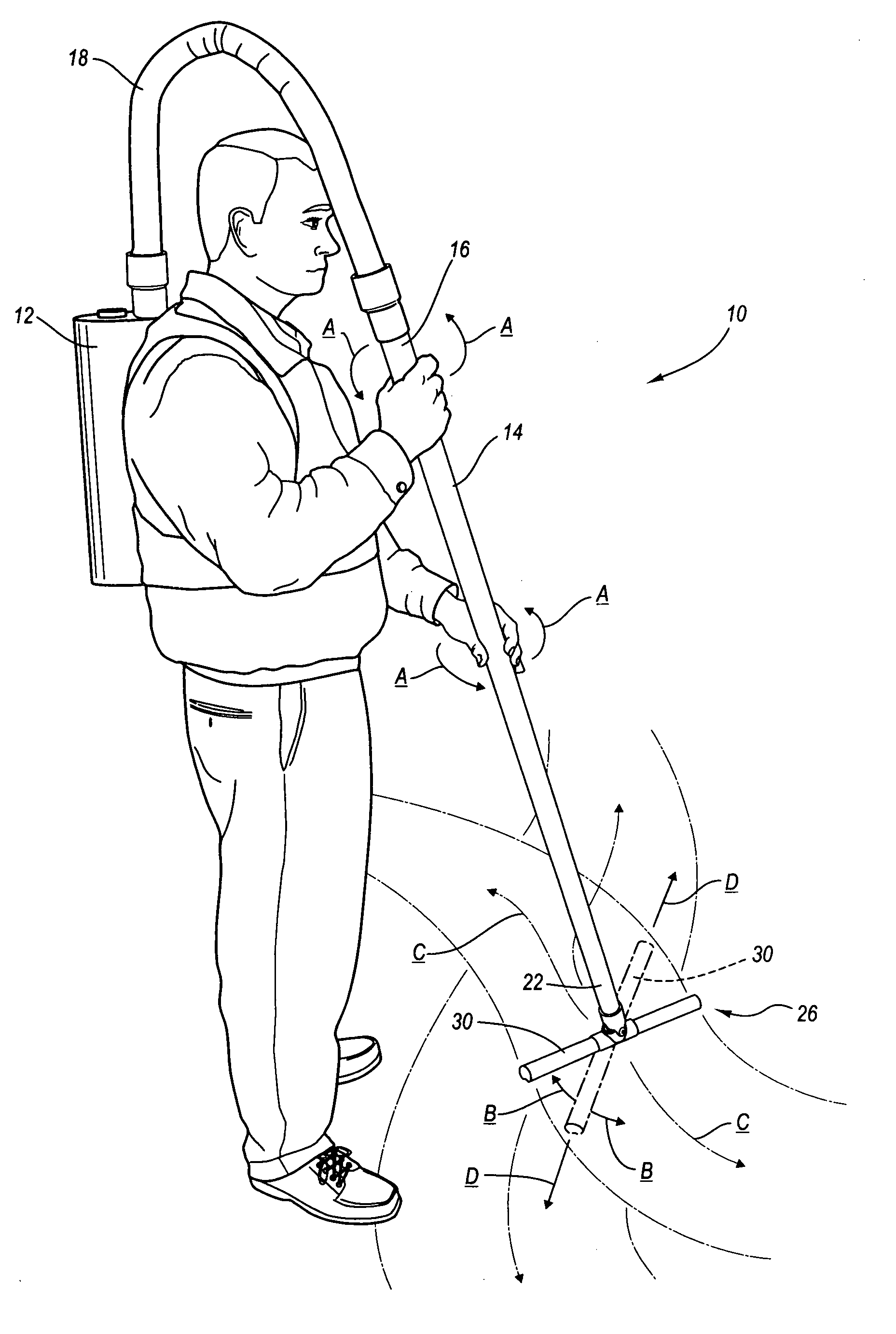
[0035] The vacuum sweeper 10 of the invention includes a power and suction unit 12, a long control tube 14, having an upper end 16 to which a flexible hose 18 is connected between the long control tube 14 and the power and suction unit 12. A lower end 22 of the long control tube 14 is connected to a vacuum head 26.

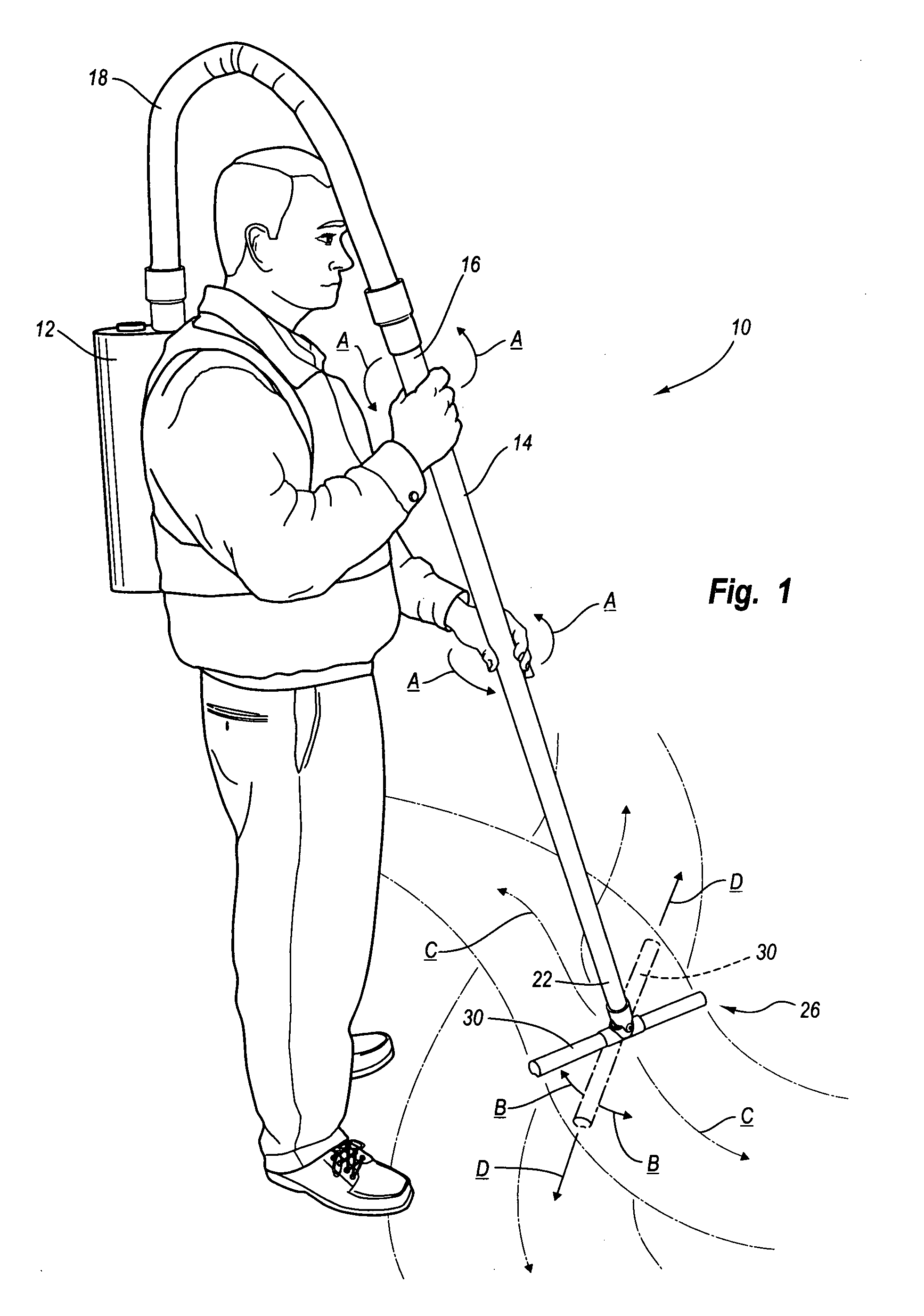
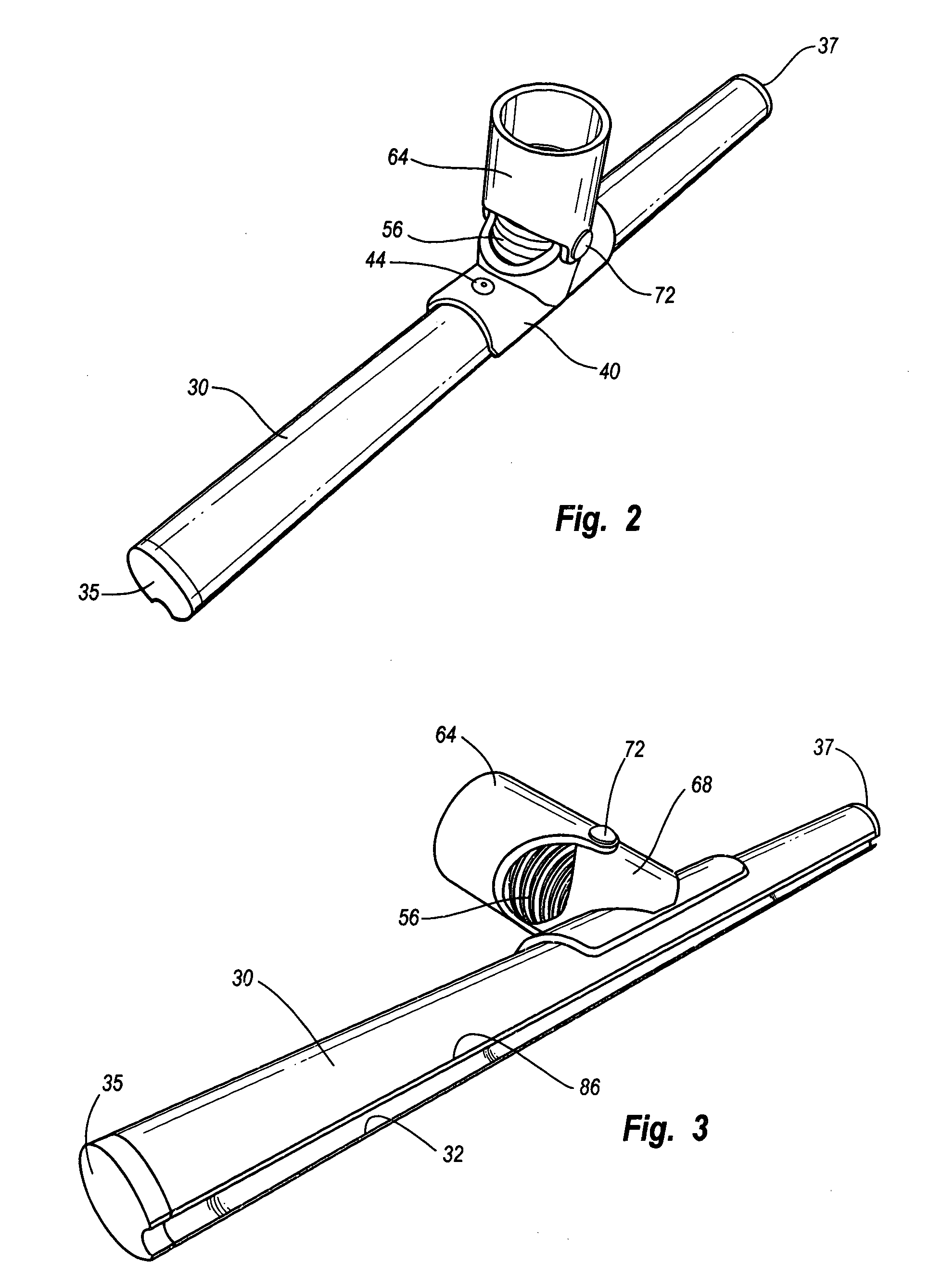
[0036] Vacuum head 26 includes a elongate tubular, ground engaging member 30, having a slot 32 formed in a bottom surface of the vacuum head.

[0037] End plates 35 and 37 are respectively provided at opposite ends of the vacuum head and a central hole 36 is provided through a top surface 38 of the vacuum head 26.

[0038] A saddle member 40 fits over the hole 36 and is adhesively bonded, and / or is riveted with rivets 44 and 46 to the vacuum head 26.

[0039] Saddle member 40 has a collar 48 adhesively bonded, or otherwise affixed thereto. Collar 48 surrounds the hole 36 and has ears 50 and 52, respectively projecting upwardly from opposite sid...


PUM


Abstract

An attachment for portable power and suction units, including a long control tube having a length to extend from a floor to adjacent shoulder height of a standing user and a vacuum head formed from a length of tube having a slot in one side and with the ends of the slot closed; and a flexible connection between the interior of the vacuum head and the interior of a control tube to be connected to a portable power and suction unit.

Description

CROSS-REFERENCE TO RELATED APPLICATIONS [0001] Not Applicable. STATEMENT REGARDING FEDERALLY SPONSORED RESEARCH OR DEVELOPMENT [0002] Not Applicable. REFERENCE TO MICROFICHE APPENDIX [0003] Not Applicable. BACKGROUND OF THE INVENTION [0004] 1. Field of the Invention [0005] This invention relates to vacuum cleaners and particularly to the hose and nozzle structures for such vacuum cleaners. [0006] 2. Description of the Related Art [0007] There have been a great many portable vacuum cleaners developed in the past for use in the care and cleaning of floor materials. Many of the portable vacuum cleaners developed in the past have been intended for use in picking up dirt and debris from carpets and other floor coverings and even from wooden floors. [0008] In the use of portable vacuum cleaners, particularly for commercial purposes, i.e., in public buildings, such as hotels, office buildings and other such structures, it becomes very necessary that the floor cleaning operations be made as...

Claims


Application Information

Patent Timeline
Patent Type & Authority Applications(United States)
IPC IPC(8): A47L5/00A47L5/36A47L9/02A47L9/06A47L9/24
CPCA47L5/36A47L9/02A47L9/242A47L9/0673A47L9/06
Inventor WERTZ, ROBERT
Owner JANPRO PROD LLC
Why Eureka
Try Eureka