
Patient Transfer System

a patient transfer and patient technology, applied in the field of patient transfer systems, can solve the problems of moving partially or completely incapacitated patients, high risk, and inability to meet the needs of patients, and achieve the effects of reducing the risk of injury, and increasing the risk of injury

Inactive Publication Date: 2017-09-14
LLANES RUDY
View PDF4 Cites 4 Cited by
  • Summary
  • Abstract
  • Description
  • Claims
  • Application Information

AI Technical Summary

Benefits of technology

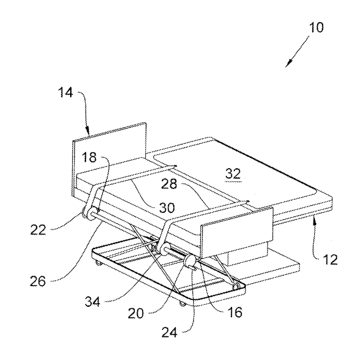
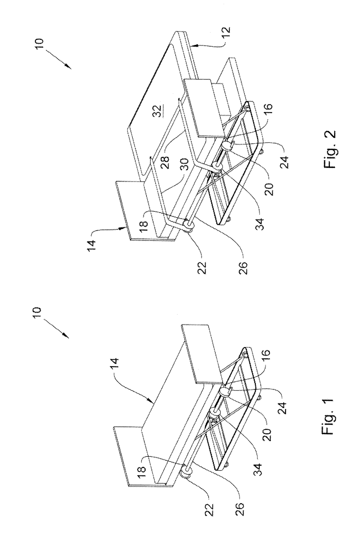
The present invention is a patient transfer system that allows for easy and smooth transfer of patients from an operating table to a recovery bed without physical strain on hospital personnel. The system includes a sheeting material that is positioned over the operating table and secured to the floor of the recovery bed using support members. A cranking mechanism is used to pull the sheeting material and the patient from the operating table to the recovery bed. This system allows for a seamless transfer of patients from the operating table to the recovery bed.

Problems solved by technology

Health care workers at hospitals, nursing homes, and home care programs face the challenge of moving partly or completely incapacitated patients.
These activities often create unacceptable risks of injury, almost without regard to the number of health care workers used in the patient transfer.
The risks are particularly high when a sufficient number of workers is not available to assist in a patient transfer.
Several complex and expensive attempts have been made in the past to provide a means for transferring a hospitalized patient from his bed to a movable, roll around platform or gurney or between such a platform and any other horizontal surface.
The task of conveying a patient under such circumstances is further hindered by the soft deformable nature of the bed or other padded surface.
Prior attempts to solve these difficulties have generally involved complex pulling and support mechanisms or bed attachments which are relatively expensive and which are cumbersome and difficult to store when not in use.

Method used


Image

  • Patient Transfer System
  • Patient Transfer System

Examples


Embodiment Construction

[0011]The present invention, hereinafter referred to as a Patient Transfer System, indicated generally at 10, transfers a post-surgical patient from the operating table 12 to a recovery table 14 or gurney, easily, smoothly, and without physical strain on the part of hospital personnel. Incorporated into a gurney or wheeled hospital bed 14, the Patient Transfer System 10 makes the transfer of patients easier on both the patient and on the staff who transfer them from the operating table 14 to the recovery bed 12.

[0012]The Patient Transfer System 10 of the present invention includes a first support member 16 and a second support member 18 extending in a generally outward direction from the wheeled hospital bed 14 or gurney (the bed to which the patient is to be transferred from the operating table 12). The first support member 16 and the second support member 18 are spaced from each other and mounted to one side of the hospital bed 14. Preferably, the first support member 16 is mounte...


PUM


Abstract

A patient transfer system for transferring a patient from an operating table to a recovery bed is provided. The patient transfer system comprises first and second support members mounted to a first side of the recovery table. First and second hubs are rotatably mounted to the first and second support members, respectively. A rotatable shaft is mounted between the first and second hubs. First strap and second straps are secured to the rotating shaft with the each strap having a free end. A sheeting material is positionable over the operating table with the free ends of the straps secured to the sheeting material. A cranking mechanism rotates the rotatable shaft. Upon positioning the sheeting material on the operating table and rotating the rotatable shaft, the first and second straps spool about the rotating shaft and pull the sheeting material from the operating table to the recovery bed.

Description

CLAIM OF PRIORITY[0001]This patent application claims priority under 35 USC 119 (e) (1) from U.S. Provisional Patent Application Ser. No. 62 / 306,893 filed Mar. 11, 2016, of common inventorship herewith entitled, “Patient Transfer Mechanism and Associated Use Thereof With Operating and Recovery Beds,” which is incorporated herein by reference as though the same were set forth in its entirety.FIELD OF THE INVENTION[0002]The present invention pertains to the field of patient transfer systems, and more specifically to the field of patient transfer systems providing a hand-cranked mechanism for transferring a post-surgical patient from the operating table to a recovery table or gurney, easily, smoothly, and without physical strain on the part of hospital personnel,BACKGROUND OF THE INVENTION[0003]Health care workers at hospitals, nursing homes, and home care programs face the challenge of moving partly or completely incapacitated patients. Due to the weight of many patients, consequently...

Claims


Application Information

Patent Timeline
Patent Type & Authority Applications(United States)
IPC IPC(8): A61G7/10
CPCA61G7/1026A61G7/1057A61G7/1044
Inventor LLANES, RUDY
Owner LLANES RUDY
Learn More