Four-wheel drive work vehicle

a four-wheel drive, work vehicle technology, applied in mechanical equipment, transportation and packaging, tractors, etc., can solve the problems of large displacement, large turning radius of vehicles, and difficulty in adjusting the speed of the vehicle, so as to achieve a small turning radius and easy operation.

Active Publication Date: 2005-01-20
KUBOTA LTD
View PDF7 Cites 6 Cited by
  • Summary
  • Abstract
  • Description
  • Claims
  • Application Information

AI Technical Summary

Benefits of technology

[0008] The present invention has been made in view of the above-described state of the art. Hence, the primary object of the invention is to provide an improved construction which retains the advantage of allowing an easy and smooth small turn by automatic disengagement of a side clutch and which also allows an operator to effect a steering operation for the small turn with a light operational feel.
[0011] On the other hand, when the steerable wheels are steered by an angle exceeding or greater than the predetermined angle, in response to this steered displacement of the steerable wheels, the pivotal cam mechanism is activated, so that the clutch operating member is pivotally operated by the predetermined angle. With this, only one side clutch for the non-steerable wheel located on the inner side of that turn is automatically disengaged, so that the vehicle makes a turn to the steered direction of the steerable wheels in the three-wheel drive mode involving the steered right and left steerable wheels and the other non-steerable wheel located on the outer side of the turn. In this, in the side clutch disengaging operational range where the steerable wheels have been steered by the angle greater than the predetermined angle, the clutch operating member is operated only by the amount needed for the clutch disengaging operation. This avoids the progressive increase in the operational load with advance in the steering operation.
[0012] Therefore, the invention has achieved the intended object of providing an improved construction which retains the advantage of allowing an easy and smooth small turn by automatic disengagement of a side clutch and which also allows an operator to effect a steering operation for the small turn with a light operational feel.
[0014] Further, the first arm portion and the second arm portion can be configured to be displaced independently of each other. This renders the operating line for the right side clutch independent of the operating line for the left side clutch. Hence, this construction can eliminate a “play” means in the form of e.g. a stroke absorbing slot for preventing an operation on one line from affecting an operation on the other. Therefore, it is possible to avoid such inconvenience as clogging of the slot with a foreign object or instability of operation associated with such play mean. Thus, a constantly smooth operation can be assured.
[0015] According to another preferred invention's construction for the pivotal cam mechanism, said cam follower member of the pivotal cam mechanism comprises a pivotal cam plate having a cam face in its outer periphery, said cam member of the pivotal cam mechanism comprises a pivot member which comes into contact with said cam face, and said pivotal cam mechanism is incorporated in a transmission case accommodating said side clutches. This construction provides an additional advantage as follows. Namely, when the steerable wheels are being steered from the straight traveling condition by an angle not greater than the predetermined angle, a play is needed for preventing transmission of a clutch disengaging force to the side clutch for the inner side of the turn and a further play is needed for preventing transmission of a reverse operating force to the other side clutch for the non-steerable wheel on the outer side of the turn. In this respect, according to the above-proposed construction, such plays can be easily designed as a particular shape of the cam face to be formed in the outer periphery of the pivotal cam plate of the pivotal cam mechanism. Moreover, as this cam face is formed in the outer periphery of the cam plate, any dust or dirt adhering to the cam face can be easily removed through its contact with the pivot member movable relative to this cam face. Furthermore, as the pivotal cam mechanism having the play function for absorbing stroke is incorporated in the transmission case, the necessary operative connection between the pivotal cam mechanism and the steering mechanism can be easily realized by simply interconnecting these mechanism without any intervention of a link member or any mechanical looseness therebetween. Such “tight” or proximal interconnection is advantageous for avoiding trouble due to adhesion of dust or dirt thereto.
[0017] Further, said pivotal cam plate can include a stable cam face portion formed in the cam face for maintaining the side cutch at a predetermined clutch disengaging condition in response to a further steering operation of the steerable wheels after the clutch disengagement. With this, in the side clutch disengaging operational range where the steerable wheels have been steered by the angle greater than the predetermined angle, the side clutch on the inner side of the turn spring-urged in the clutch engaging direction is operated only by the amount needed for the clutch disengaging operation. This avoids the progressive increase in the operational load when the steerable wheels are further steered after the side clutch disengagement.

Problems solved by technology

This construction, however, is disadvantageous in that the minimum turning radius of the vehicle tends to be relatively large, which presents difficulty in an operation on a limited lawn-covered land or a land having a complicated ground contour.
However, when the vehicle effects a small turn by applying a braking force to the inner side rear wheel with the side brake, there occurs a forcible “dragging” displacement of the rear wheel locked by the side brake, which displacement tends to roughen up the traveling ground or damage the lawn in the case of a lawn mower vehicle.
If the vehicle is constructed as a rice planting machine, such small turn roughens the land at the ridge end of the field where the turn is effected.
This construction, however, has a structural difficulty as follows.

Method used


Image

  • Four-wheel drive work vehicle
  • Four-wheel drive work vehicle
  • Four-wheel drive work vehicle

Examples


Embodiment Construction

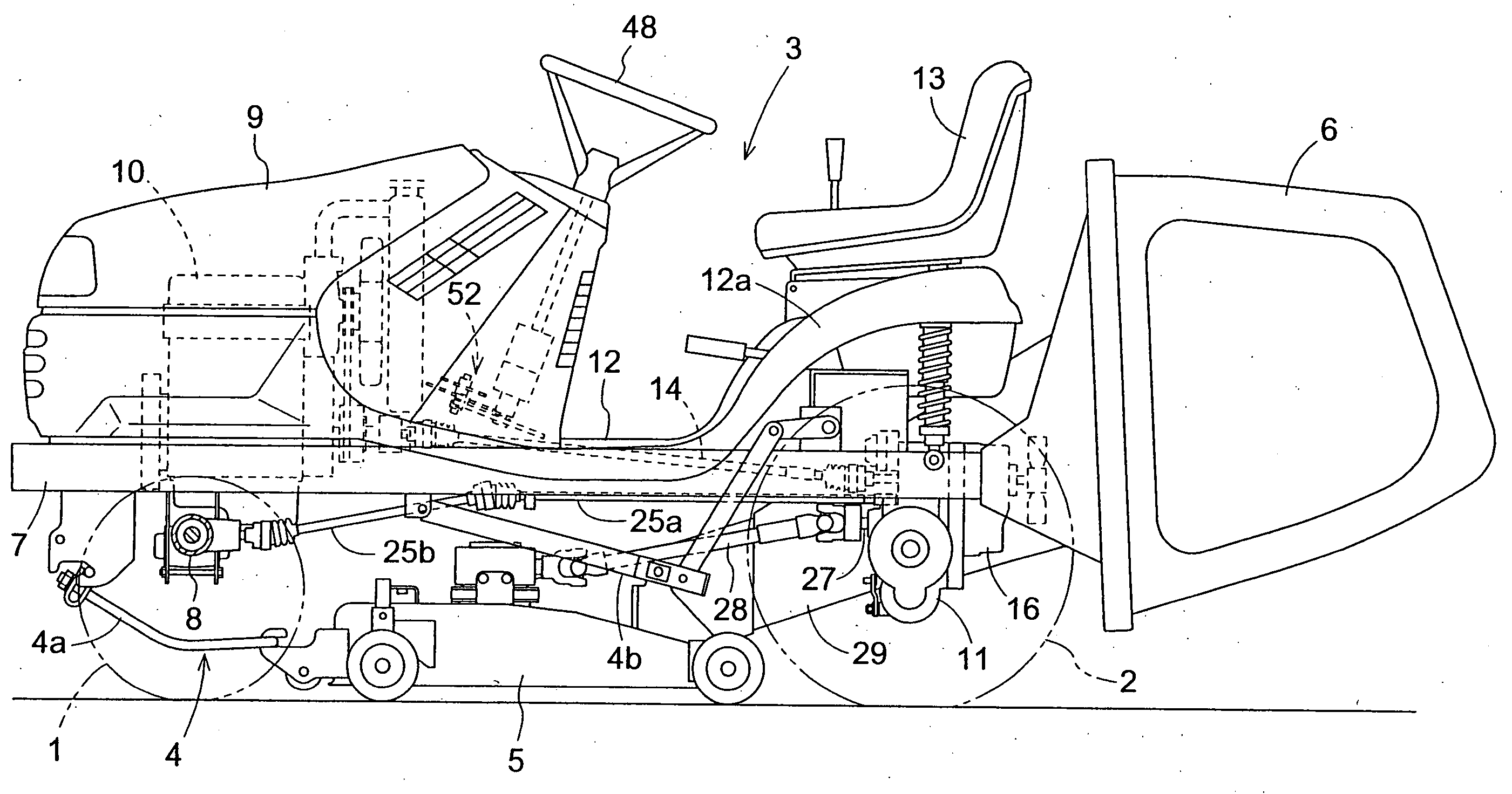
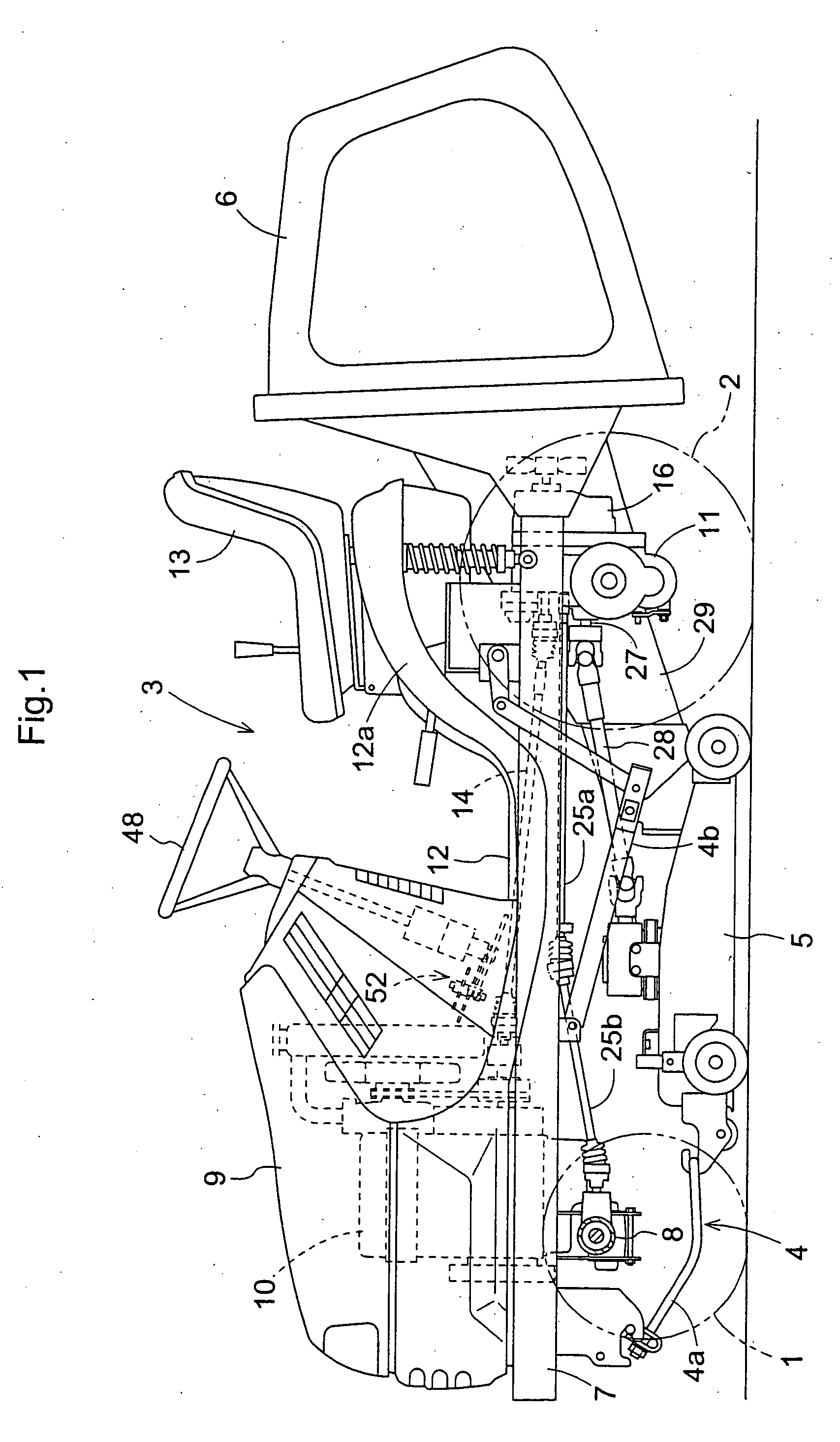
[0038]FIG. 1 is an overall side view showing a passenger-driven lawn mower vehicle as an example of a work vehicle relating to the invention. This passenger-driven lawn mower vehicle includes a passenger-driven traveling vehicle body 3 provided as a four-wheel drive type including front wheels 1 as steerable wheels and rear wheels 2 as non-steerable wheels. To the bottom of the vehicle body 3, there is suspended a mower implement 5 via a quadruple link mechanism 4 consisting of front links 4a and rear links 4b, such that the mower implement 5 can be lifted up and down. To the rear of the vehicle body, there is connected a grass collecting container 6 for collecting lawn or grass cut by the mower implement 5.

[0039] The vehicle body 3 mounts thereon a pair or right and left main frames 7. To the front of these frames 7, there is mounted a front axle case 8 steerably mounting the front wheels 1 to the right and left ends thereof, with the axle case 8 being capable of rolling movement ...


PUM


Abstract

A four-wheel drive work vehicle includes an engine, a pair of right and left steerable wheels rotatably driven by receiving power from the engine via a differential mechanism, a pair of right and left non-steerable wheels rotatably driven by receiving power from the engine via right and left side clutches and a pivotal cam mechanism for operating a clutch operating member for controlling the side clutch based on a steered displacement of the steerable wheels. The pivotal cam mechanism includes a cam member which is displaced based on the steered displacement and a cam follower member operably associated with the cam member. The clutch operating member is displaced via the pivotal cam mechanism by a predetermined amount in response to a steering operation of the steerable wheels by an angle exceeding a predetermined angle from a straight traveling condition and in association with the displacement of the clutch operating member by the predetermined amount, one side clutch for one of the non-steerable wheels located on the inner side of the vehicle turn is automatically disengaged against an engaging urging force.

Description

BACKGROUND OF THE INVENTION [0001] 1. Field of the Invention [0002] The present invention relates to a four-wheel drive work vehicle including a pair of right and left front wheels rotatably driven by receiving power from an engine via a differential mechanism and a pair of right and left non-steerable rear wheels rotatably driven by receiving power from the engine via right and left side clutches, the side clutches being operated by a clutch operating member which is controlled based on a steered displacement of the front wheels. [0003] 2. Description of the Related Art [0004] With a four-wheel drive lawn mower, in general, the right and left front wheels as steerable wheels are driven via a differential mechanism whereas the rear wheels as non-steerable wheels are driven via a differential mechanism having a differential lock function (see e.g. Japanese Patent Application “Kokai” No.: 2003-106412). Further, the convention has also proposed a construction which provides side brakes...

Claims


Application Information

Patent Timeline
Patent Type & Authority Applications(United States)
IPC IPC(8): A01D69/00B60K17/34B62D11/24B62D49/06
CPCA01D69/00B60K17/34B60Y2200/223B62D11/24Y10T74/2107Y10T74/2101Y10T74/20408Y10T74/2045Y10T74/20462B62D49/0671F16C2310/00
Inventor UEMURA, KATSUHIKOOGASAWARA, HIROYUKINAGAI, HIROKI
Owner KUBOTA LTD
Why Eureka
Try Eureka