Bicycle handlebar clock mounting structure

a technology for handlebars and bicycles, applied in the direction of steering devices, mechanical control devices, instruments, etc., can solve the problems of tubular profile handlebars, easy falling off of said clocks, and inability to fully mount clocks to the surface, etc., to achieve the effect of practicality and convenience of clock installation

Inactive Publication Date: 2005-08-04
WEI HAU ACCESSORIES
View PDF14 Cites 13 Cited by
  • Summary
  • Abstract
  • Description
  • Claims
  • Application Information

AI Technical Summary

Benefits of technology

[0006] The primary objective of the invention herein is to provide a bicycle handlebar clock mounting structure that is installed onto the bar member comprising various different model handlebars in which the clock mount is an inverted U-shaped construct and, furthermore, an end section extends inward from each of its two lateral extremities, an elongated adjustment hole is formed in each of the two end sections, and the center portion of the clock mount is of a regular tubular profile; a recessed arcuate surface is fabricated along the underside of the clock enables sturdy placement against the center portion of the clock mount; after screws are inserted through the adjustment holes in the end sections of the clock mount, the screws are tightened to attach various shape handlebars to the bicycle by means of clamp cover at the front end of the stem, enabling the clock mount to be widely utilized on a range of various bend handlebars and thereby achieving clock installation practicality and convenience.

Problems solved by technology

However, as the recessed arcuate surface under the clock only provides for attachment to handlebars having a regular tubular profile and existing handlebars are not only available in such consistent tubular profiles, when fitted on current designs of differently shaped handlebars, as indicated in FIG. 1-A and FIG. 1-B, the clock A cannot be fully mounted onto the surface of the said irregular tubular profile handlebar B such that when a bicycle so equipped travels over rough roads, the said clock A readily falls off due to insufficient surface area adhesion during continuous vibration.

Method used


Image

  • Bicycle handlebar clock mounting structure
  • Bicycle handlebar clock mounting structure
  • Bicycle handlebar clock mounting structure

Examples


Embodiment Construction

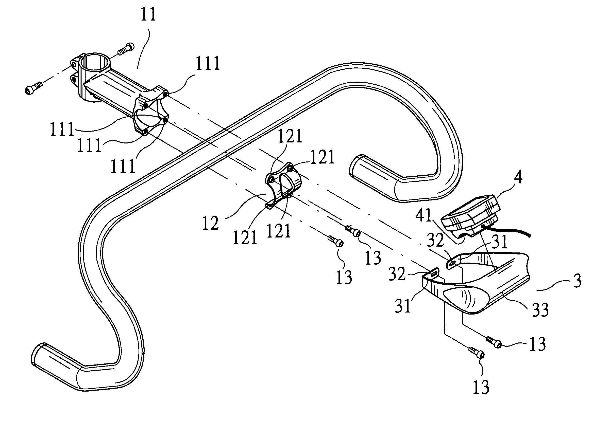
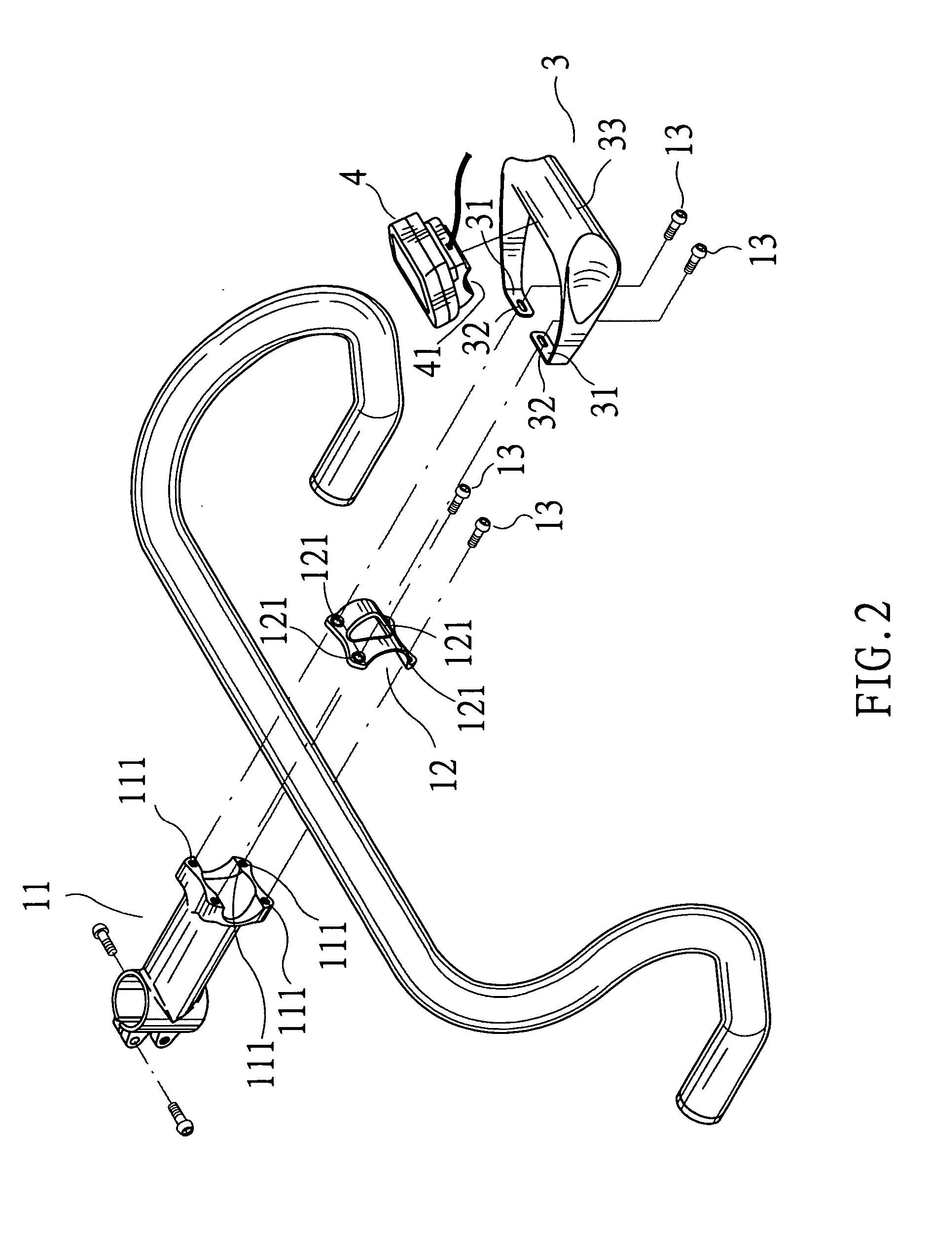
[0014] Referring to FIG. 2 and FIG. 3, the bicycle handlebar clock mounting structure of the invention herein is installed onto the anterior aspect of the bar member comprising various different model handlebars 2, the clock mount 3 is an inverted U-shaped construct and, furthermore, an end section 31 extends inward from each of its two lateral extremities, an elongated adjustment hole 32 is formed in each of the two end sections 31 and, furthermore, the center portion of the clock mount 3 is of a regular tubular profile 33; and a recessed arcuate surface 41 is fabricated along the underside of the clock 4.

[0015] As such, when preparing to assemble various different style bend handlebars 2 and 2′ (as shown in FIG. 3 and FIG. 5) between the bicycle 1 stem 11 and clamp cover 12 (as shown in FIG. 4-A and FIG. 4-B), after the screws 13 for fastening together the stem 11 and the clamp cover 12 are first inserted through 121 holes of the clamp cover 12 as well as the adjustment holes 32 ...


PUM


Abstract

A bicycle handlebar clock mounting structure installed onto the bar member comprising various different model handlebars. The clock mount is an inverted U-shaped construct and, furthermore, an end section extends inward from each of its two lateral extremities, an elongated adjustment hole is formed in each of the two end sections, and the center portion of the clock mount is of a regular tubular profile. A recessed arcuate surface fabricated along the underside of the clock enables sturdy positioning against the center portion of the clock mount. After screws are inserted through the adjustment holes in the end sections of the clock mount, the screws are tightened to attach various shape handlebars to the bicycle by means of clamp cover at the front end of the stem, enabling the clock mount to be widely utilized on a range of various style handlebars and thereby achieving clock installation practicality and convenience.

Description

BACKGROUND OF THE INVENTION [0001] 1) Field of the Invention [0002] The invention herein relates to bicycle accessories, specifically a bicycle handlebar clock mounting structure that provides for clock installation on various model handlebars and thereby achieves installation practicality and convenience. [0003] 2) Description of the Prior Art [0004] In the conventional installation of clocks on bicycle handlebars, since a recessed arcuate surface is typically fabricated along the underside the said clock, a double-sided adhesive plastic tape affixes it to the surface of the handlebar bar member. However, as the recessed arcuate surface under the clock only provides for attachment to handlebars having a regular tubular profile and existing handlebars are not only available in such consistent tubular profiles, when fitted on current designs of differently shaped handlebars, as indicated in FIG. 1-A and FIG. 1-B, the clock A cannot be fully mounted onto the surface of the said irregu...

Claims


Application Information

Patent Timeline
Patent Type & Authority Applications(United States)
IPC IPC(8): B62J11/00B62K19/40G05G11/00
CPCY10T74/20822B62J11/00
Inventor HUANG, YUAN-HSIN
Owner WEI HAU ACCESSORIES
Why Eureka
Try Eureka