
Magnetic identification card clip

a magnetic identification and clip technology, applied in the field of magnetic identification card clips, can solve the problems of affecting the effect of the face recognition on the photo, affecting the quality of the photo, and affecting the effect of the alligator clip on many types of garments

Inactive Publication Date: 2005-08-04
TARAS CURT MICHAEL
View PDF5 Cites 10 Cited by
  • Summary
  • Abstract
  • Description
  • Claims
  • Application Information

AI Technical Summary

Benefits of technology

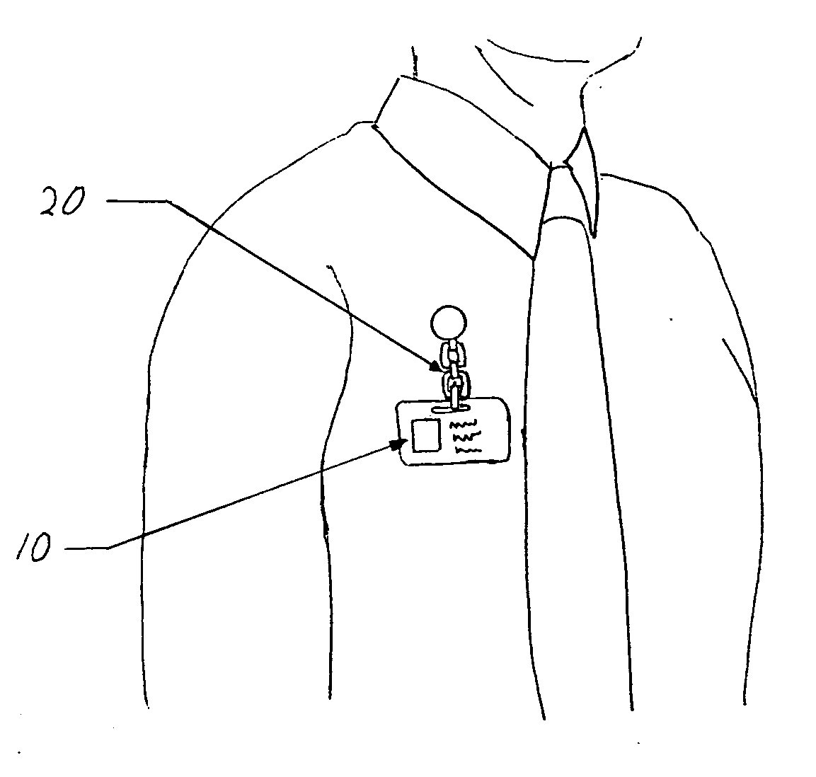
[0011] The new invention described by this patent is an enhancement over existing devices because it has several distinct advantages. One advantage is this invention provides unlimited attachment possibilities. The invention can be attached anywhere on a garment and is not limited to being attached to pockets or lapels. This allows photo identification cards to be positioned in the ideal location near the breast for quick comparisons of the photo to the face. The procedure for attaching the invention to a garment is similar to placing a magnet on a refrigerator. A second advantage is the invention is self straightening. The invention hangs an ID card on the person much like a closet hanger hangs a garment. The single magnetic connector acts as a pivot point in conjunction with the bendable strap to allow the weight of the ID to self correct alignment. The combined feature of the magnetic pivot point and the bendable strap allow minor movements of the assembly but keep the ID card secure and close to the wearer A third advantage of the invention is logo display. This invention provides a surface for the display of a logo emblem on its front face. The combination of a logo emblem with an identification card strap is a novel creation. The functions of a logo pin are combined with the utility of a identification card clip to further enhance the appearance and recognition of employees and other people wearing ID cards. Previously a logo pin and an identification card clip were separate items. Now with this invention they have been combined into one clean looking assembly.
is logo display. This invention provides a surface for the display of a logo emblem on its front face. The combination of a logo emblem with an identification card strap is a novel creation. The functions of a logo pin are combined with the utility of a identification card clip to further enhance the appearance and recognition of employees and other people wearing ID cards. Previously a logo pin and an identification card clip were separate items. Now with this invention they have been combined into one clean looking assembly.

Problems solved by technology

Currently available devices to perform this task include clips, pins, adhesive, and lanyards, all which have limitations.
The ID is then sometimes clipped to a belt or a pants pocket which is often out of view making effective recognition of the face to the photo difficult.
These renders the alligator style clip ineffective for many types of garments.
Pins penetrate clothing and can damage fabric by leaving a hole.
Pins are also troublesome to attach and remove from clothing while it is being worn.
This produces an unsightly bump behind thin fabric and can be uncomfortable when worn against bare skin.
These adhesive backed tags are often disposable and have too weak of a bond to hold the common plastic photo ID card.
The bond of adhesive only lasts for a few uses and progressively weakens each time.
Lanyards can carry plastic photo ID cards with ease but they can be unfashionable and a distraction to wear.
Lanyards do not look attractive on finely tailored business attire.
Lanyards can also be uncomfortable and distracting.
They wear on the neck, dangle in the way of tasks, and can get caught in or on equipment.

Method used


Image

  • Magnetic identification card clip
  • Magnetic identification card clip
  • Magnetic identification card clip

Examples


Embodiment Construction

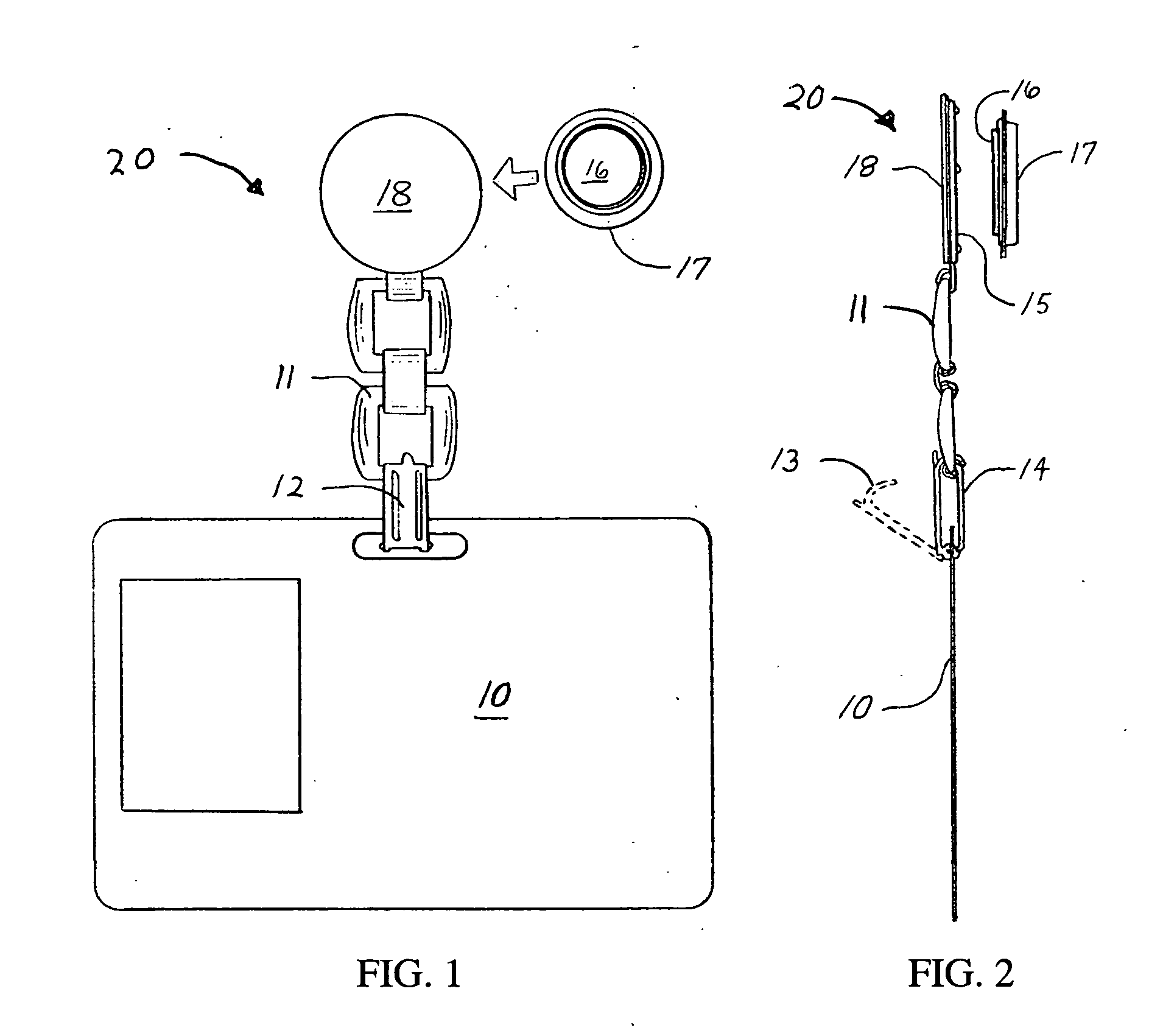
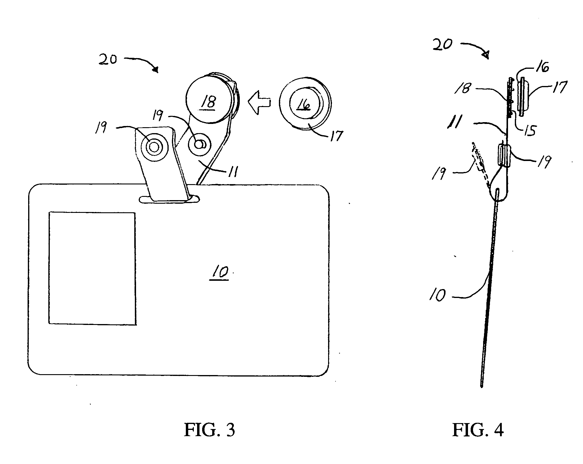
, components are identified by numbers which are the same throughout the several views. FIGS. 1 and 2 illustrate the metal embodiment of the invention connected to an identification card 10. In this embodiment a linked metal bendable strap 11 is comprised of hinged metal links connected to one another like a chain. The bendable strap links the card attachment clasp 12 to the ferrous metal plate 13 of the two part magnetic connector. The bendable strap 11 can articulate to accommodate multiple changes of position and angle of the magnetic clip assembly 17. The card attachment clasp 12 in the metal embodiment is a modified foldover clasp which is a design used in bracelets and watch bands. To attach the invention to an identification card 10 the toothed arm of the card attachment clasp 12 is threaded through a slot cut in the identification card 10. This is shown by the dashed alternative position of the clasp's toothed arm. The toothed arm is then folded closed until the tooth engage...


PUM


Abstract

A clip that utilizes a magnet to attach identification cards to clothing. The clip includes a clasp, a bendable strap, and a magnetic connector which together allow identification cards to be displayed anywhere on a garment without penetrating, clamping or biting the fabric. The invention is connected to an identification card by passing the card attachment clasp through a slotted hole cut in the card and snapping it closed. The clasp is attached to a bendable strap that ties the card to the magnetic connector. The bendable strap can bend and flex allowing the position of displayed card to adjust to the movement of the person wearing it. The magnetic connector consists of 2 parts. The first part is a ferrous metal plate which is fixed to the back of the bendable strap. The second part is an extra strong magnet which is placed behind clothing fabric when attaching the invention to a person's clothing. Using magnetic attraction, the two pieces of the connector hold together and sandwich clothing fabric between them. This attaches the invention and an identification card to the blank face of a garment without penetrating, clamping, or biting the fabric.

Description

REFERENCES CITED [0001]6,684,544 B1*February 2004Buettell40 / 6616,006,455*December 1999Miller40 / 1.6BACKGROUND OF THE INVENTION [0002] This invention relates to a magnetic clip used to attach items to garments, and more specifically to a magnetic clip for attaching an identification card to clothing for display. [0003] Identification cards are increasingly required to be displayed on clothing for security and occupational related purposes. Employers and government agencies have policies that require the wearing of a photo ID to control access to secure areas and aid in employee identification. Due to these policies and security procedures there is a need for identification card display devices that are easy to use, compact, and functional. One of the primary functions of such a device is to position the ID card in a visible location on a person in close relation to their face. This positioning is important so an effective ID check can be made. The ideal location for this is on or near...

Claims


Application Information

Patent Timeline
IPC IPC(8): A44C3/00G06K5/00
CPCA44D2203/00A44C3/001A45F5/02
Inventor TARAS, CURT MICHAEL
Owner TARAS CURT MICHAEL
Learn More