Pressure actuated safety valve with spiral flow membrane

a safety valve and spiral flow technology, applied in the direction of catheters, packaging, intravenous devices, etc., can solve the problems of small amounts of blood oozing into the proximal end of the catheter, dialysis sessions, and inpracticality and dangerous catheter inserting and removal,

a safety valve and spiral flow technology, applied in the direction of catheters, packaging, intravenous devices, etc., can solve the problems of small amounts of blood oozing into the proximal end of the catheter, dialysis sessions, and inpracticality and dangerous catheter inserting and removal,

US20050171510A1Inactive Publication Date: 2005-08-04NAVILYST MEDICAL

Image

  • Pressure actuated safety valve with spiral flow membrane
  • Pressure actuated safety valve with spiral flow membrane
  • Pressure actuated safety valve with spiral flow membrane

Examples


Embodiment Construction

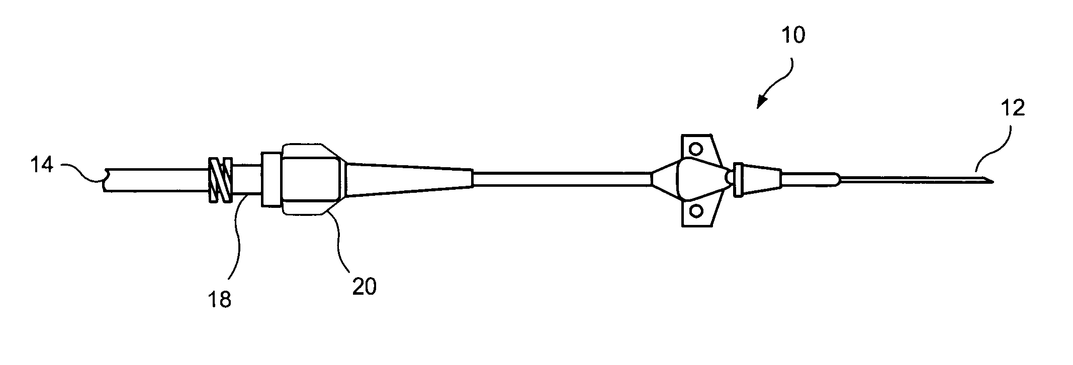
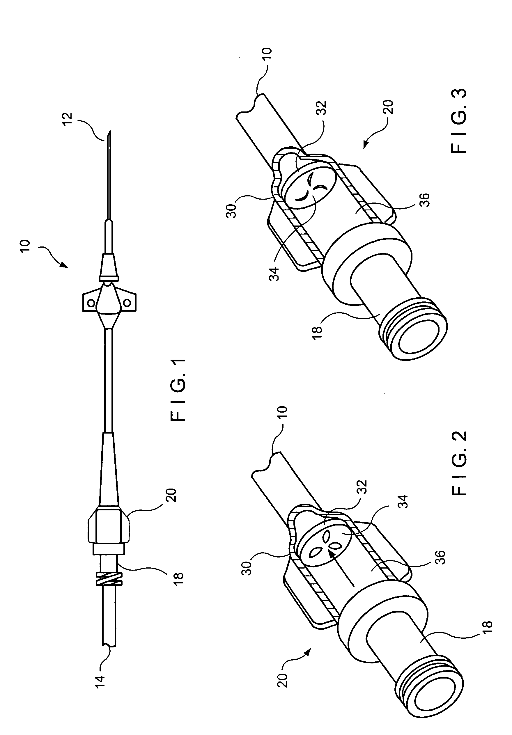
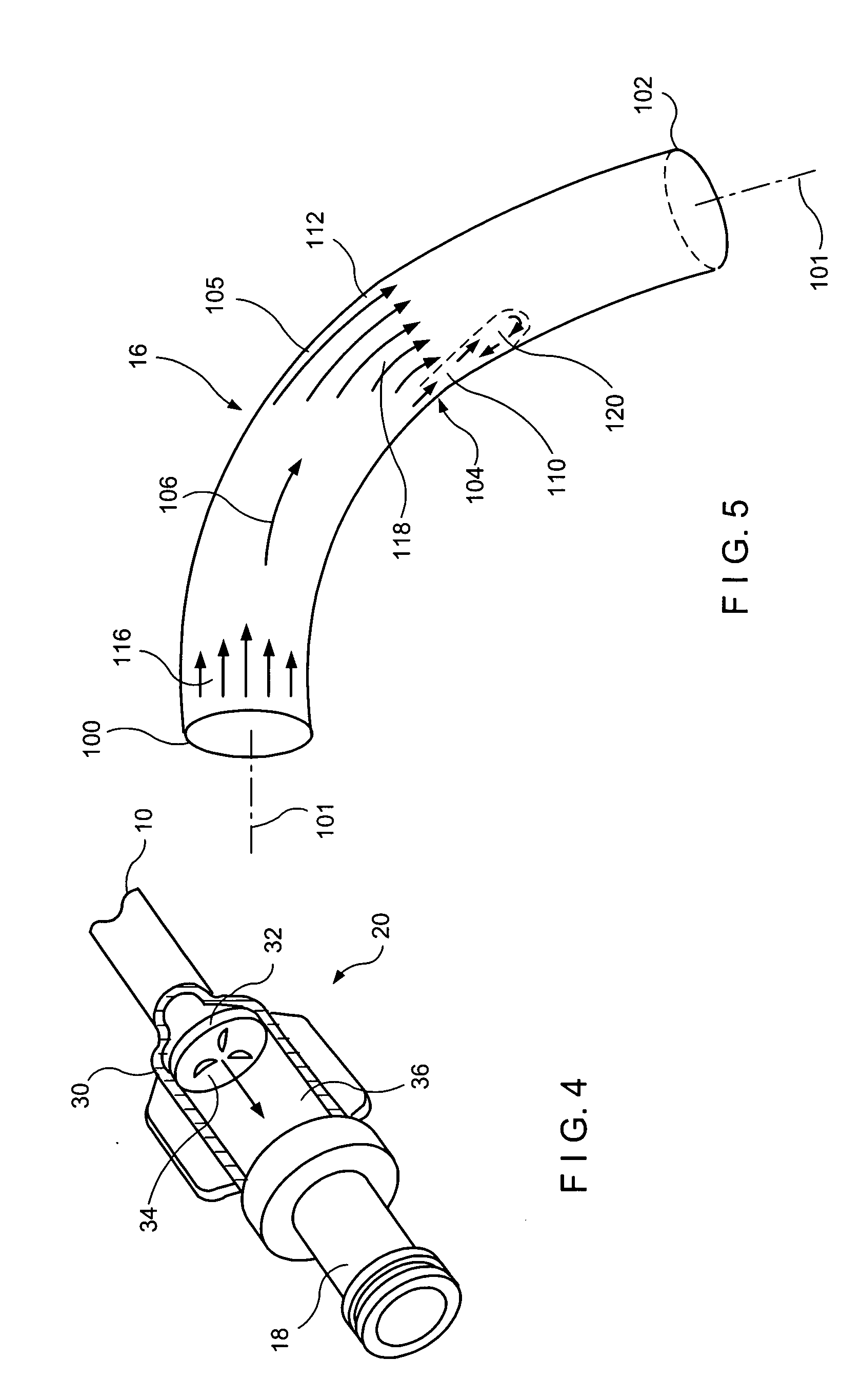
[0016] The present invention may be further understood with reference to the following description and the appended drawings, wherein like elements are referred to with the same reference numerals. The present invention is related to medical devices used to access the vascular system of a patient, and in particular to central line catheters used for chronic access to a vein or artery.

[0017] Semi-permanently placed catheters may be useful for a variety of medical procedures which require repeated access to a patient's vascular system in addition to the dialysis treatments mentioned above. For example, chemotherapy infusions may be repeated several times a week for extended periods of time. For safety reasons, as well as to improve the comfort of the patient, injections of these therapeutic agents may be better carried out with an implantable, semi-permanent vascular access catheter. Many other conditions that require chronic venous supply of therapeutic agents, nutrients, blood prod...


PUM


Abstract

A pressure actuated valve, comprises a flow chamber having an inlet and an outlet and a resilient membrane extending across the flow chamber to selectively impede passage of a fluid between the inlet and the outlet. The membrane includes at least one slit formed therein so that, when a fluid pressure to which the membrane is subjected is at least a predetermined threshold level, edges of the at least one slit separate to permit fluid flow therethrough. The at least one slit has a first curvature in a surface plane of the membrane and a second curvature along a thickness of the membrane to impart a rotational velocity component to a flow of fluid therethrough relative to a centerline of the flow chamber.

Description

[0001] The present application incorporates by reference the entire disclosure of U.S. Application entitled ā€œPressure Activated Safety Valve With Anti-Adherent Coatingā€ filed on even day herewith naming Karla Weaver and Paul DiCarlo as inventors, and U.S. Application entitled ā€œStacked Membrane For Pressure Actuated Valveā€ filed on even day herewith naming Karla Weaver and Paul DiCarlo as inventors, and U.S. Application entitled ā€œPressure Activated Safety Valve With High Flow Slitā€ filed on even day herewith naming Karla Weaver and Paul DiCarlo as inventors, and U.S. Application entitled ā€œDual Well Port Deviceā€ filed on even day herewith naming Katie Daly, Kristian DiMatteo and Eric Houde as inventors. BACKGROUND OF THE INVENTION [0002] Many medical procedures require repeated and prolonged access to a patient's vascular system. For example, during dialysis treatment blood may be removed from the body for external filtering and purification, to make up for the inability of the patien...

Claims


Application Information

Patent Timeline
04 Aug 2005
Publication
US20050171510A1
IPC
A61M25/00; A61M39/22; A61M39/24; B65D47/20
CPC
A61M39/24; A61M2039/2426; A61M2039/242
Inventors
DICARLO, PAUL; WEAVER, KARLA