Vehicle headlamp

Inactive Publication Date: 2005-08-11
KOITO MFG CO LTD
View PDF6 Cites 11 Cited by
  • Summary
  • Abstract
  • Description
  • Claims
  • Application Information

AI Technical Summary

Benefits of technology

[0026] In this case, in the event that a second additional reflector is provided laterally outwardly of the additional reflector for reflecting light from the light source towards the extended reflecting surface portion of the additional reflector, whereby a second additional light-distribution pattern is formed by reflected light from the second additional reflector which second additional light-distribution pattern partially overlaps a laterally outward end portion of the additional light-distribution pattern, the diffused area of the low beam light-distribution pattern can be expanded further laterally outwardly of the vehicle, thereby making it possible to enhance further the visibility of the road surface situated laterally outwardly and diagonally forward of the vehicle.
[0027] As this occurs, in the event that a reflecting surface of the second additional reflector has a substantially ellipsoidal surface shape in which the light so

Problems solved by technology

However, in the vehicle headlamps described in JP-U-02-047704 and JP-A-2001-229715, since the light source bulb is inserted and fixed to the reflector on the same horizontal plane as the optical axis, there is caused the following problem.
Namely, in the projector-type vehicle headlamps, while an optical axis sideways area on a reflecting surface of the reflector is suitable for formation of a diffused area of the low beam light-distribution pattern, in the event that the light

Method used


Image

  • Vehicle headlamp
  • Vehicle headlamp
  • Vehicle headlamp

Examples


Example

[0040] An embodiment of the invention will be described below by reference to the drawings.

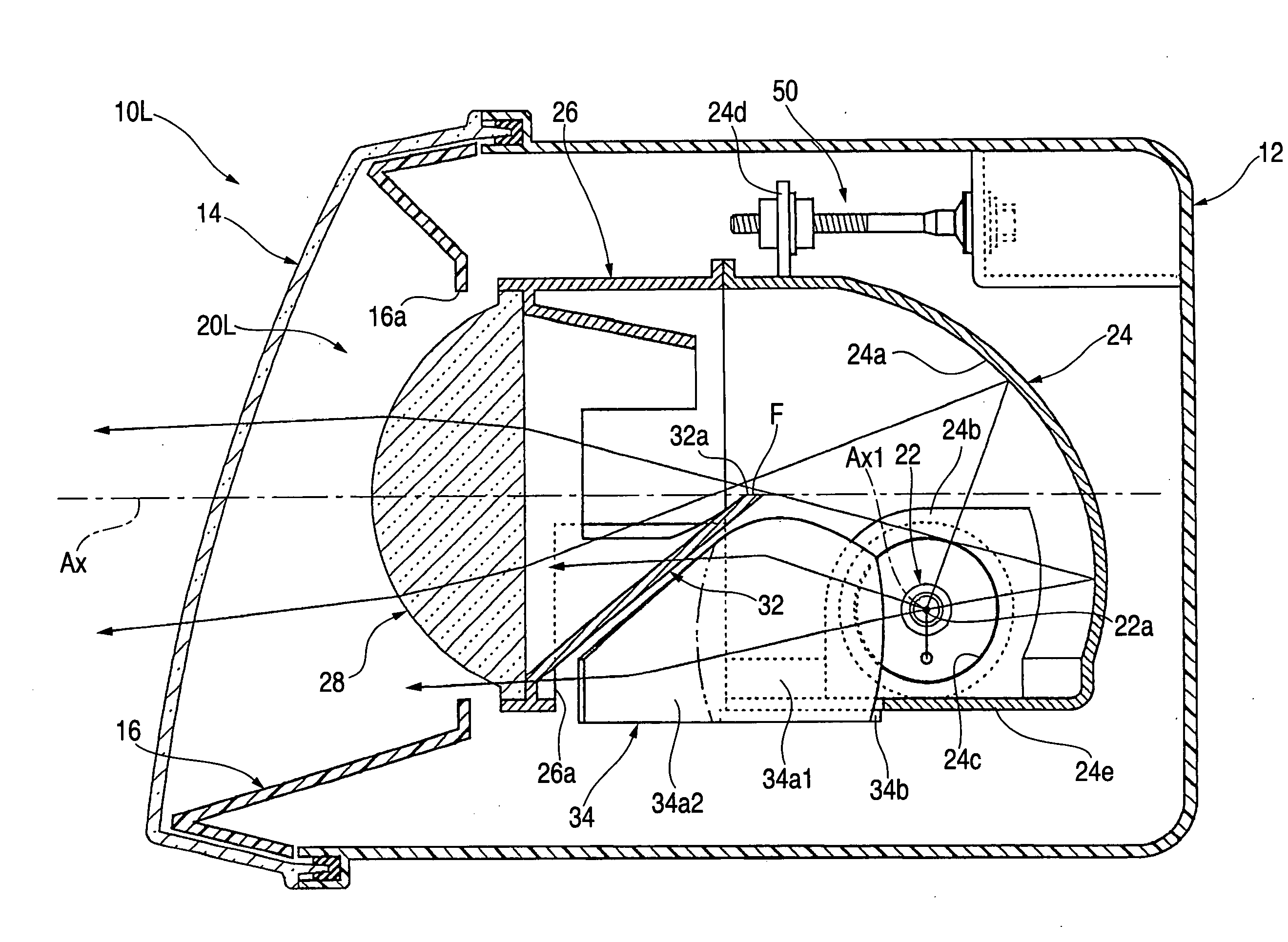
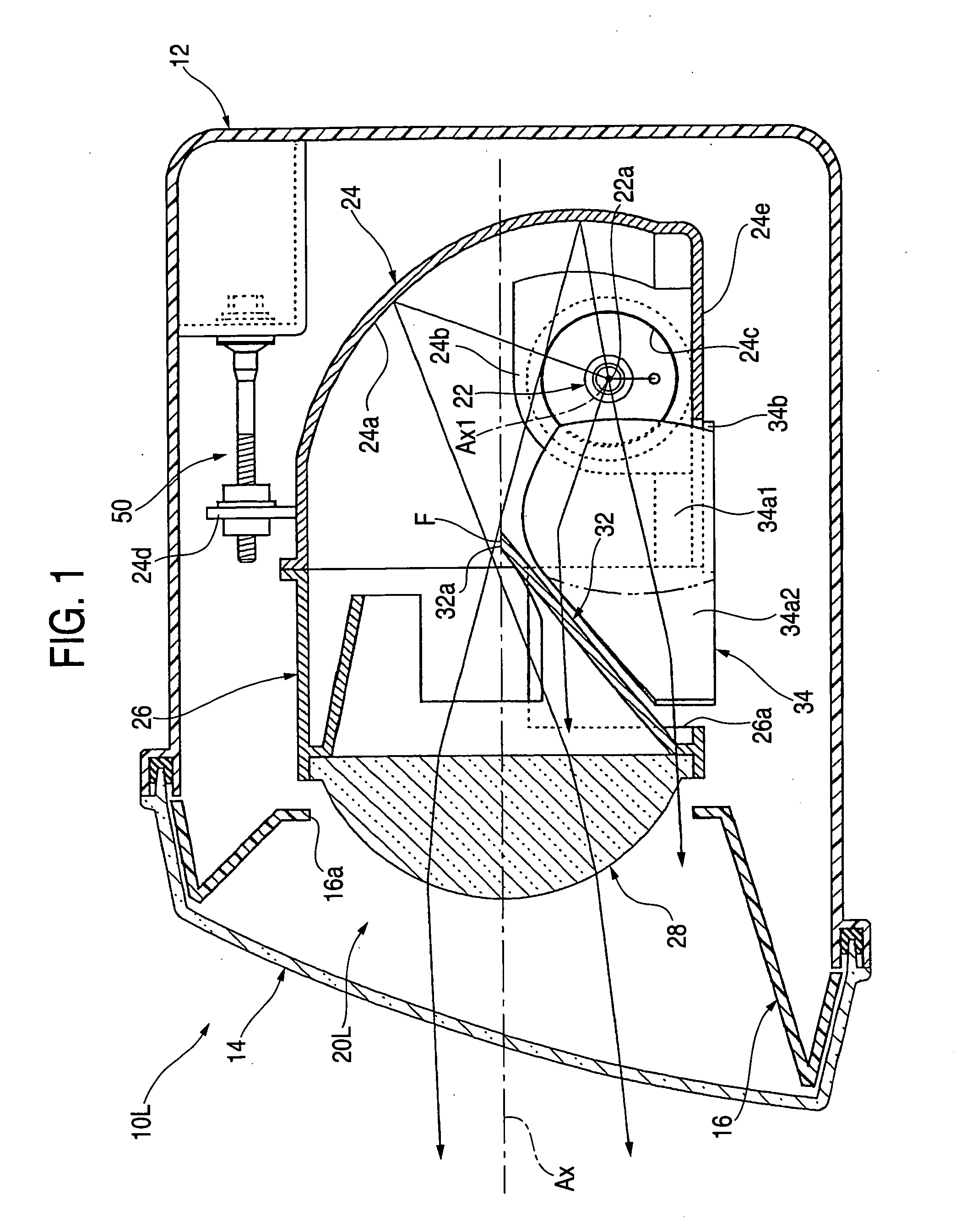
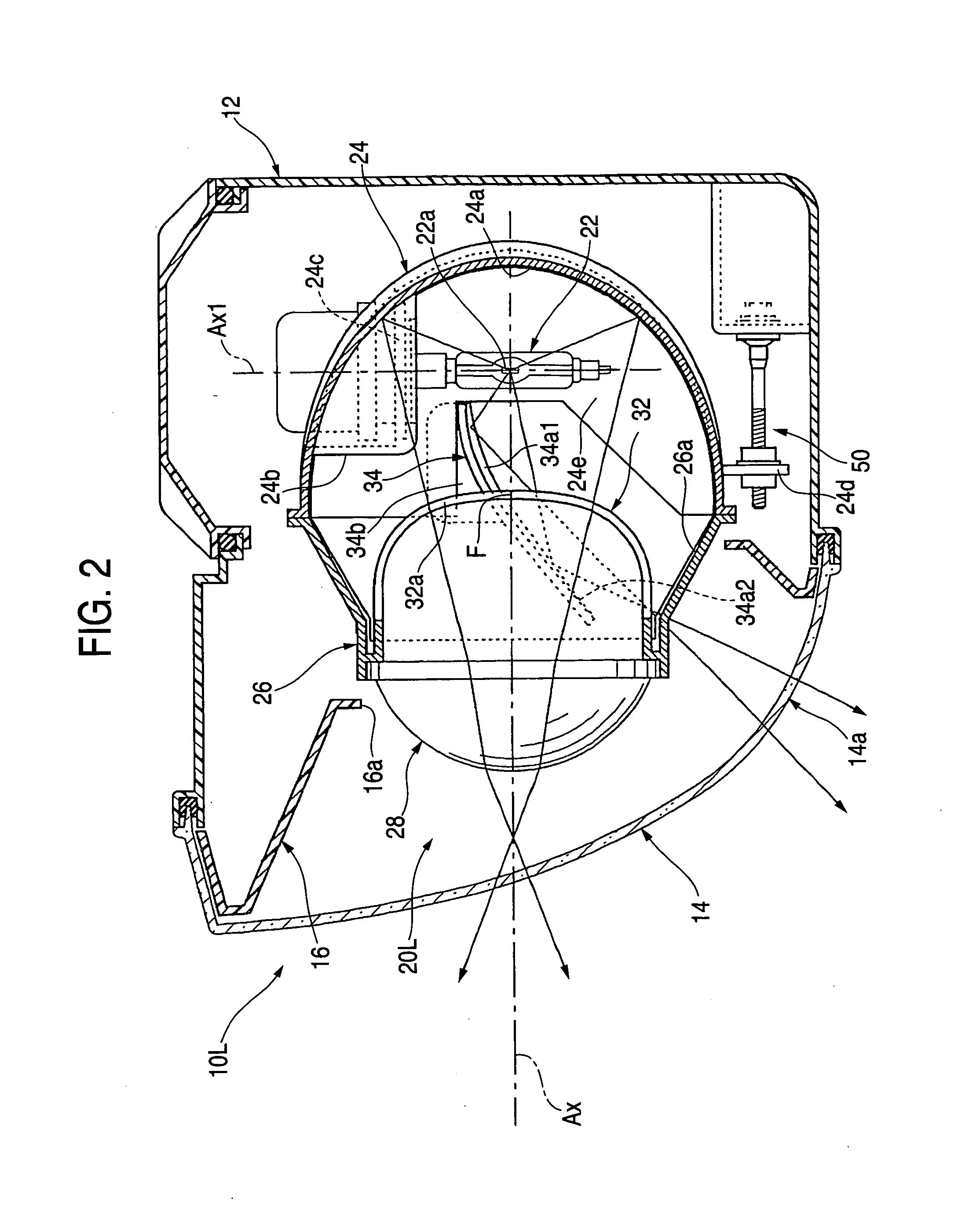
[0041]FIGS. 1 and 2 are, respectively, a vertically longitudinal section view a horizontally longitudinal section view, both of which show a left vehicle headlamp 10L according to an embodiment of the invention.

[0042] As shown in these drawings, the vehicle headlamp 10L is a lamp disposed at a left-hand side front end portion of a vehicle and is constructed such that a lamp unit 20L having an optical axis Ax extending in a longitudinal direction of the vehicle is accommodated within a lamp compartment made up of a lamp body 12 and a transparent transparence cover mounted in a front end opening in the lamp body in such a manner as to be tilted vertically and laterally via an aiming mechanism 50.

[0043] Then, in a stage where an aiming adjustment by the aiming mechanism 50 has been completed, the optical axis Ax of the lamp unit 20 is in a state where the axis extends in a downward direction a...


PUM


Abstract

By inserting a light source bulb into a reflector from a side thereof at a position apart downwardly from an optical axis, it is made possible to use an area situated on a side of the optical axis effectively for controlling the light distribution of a vehicle headlamp. In addition, by providing an additional reflector between the light source bulb and a shade for reflecting light from a light source laterally outwardly and diagonally forward of a vehicle through a gap between the reflector and a projection lens, a diffused area of a low beam light-distribution pattern is illuminated brightly and the diffused area is expanded laterally outwardly of the vehicle.

Description

[0001] The present application claims foreign priority based on Japanese Patent Application P.2004-028969, filed Feb. 5, 2004, the contents of which are incorporated herein by reference. BACKGROUND OF THE INVENTION [0002] The present invention relates to a vehicle headlamp which is constructed to emit light so as to form a low beam light-distribution pattern, and more particularly to a so-called projector-type vehicle headlamp. [0003] In general, in projector-type vehicle headlamps, a projection lens is disposed on an optical axis which extends in a longitudinal direction of a vehicle and a light source is disposed rearward of a rear-side focal point of the projection lens, whereby light from the light source is reflected towards the optical axis by a reflector. [0004] Then, JP-U-02-047704 and JP-A-2001-229715 describe the projector-type vehicle headlamps adopting a sideways insertion-type headlamp construction in which the light source is made up of a light emitting portion of a li...

Claims


Application Information

Patent Timeline
IPC IPC(8): F21S8/10F21V7/00F21W101/10F21Y101/00
CPCF21S48/1186F21S48/1388F21S48/119F21S41/173F21S41/365F21S41/172
Inventor KAGIYAMA, SHINJI
Owner KOITO MFG CO LTD
Why Eureka
Try Eureka