Ostial stent

a stent and ostial technology, applied in the field of ostial stents, can solve the problems of single stents being incapable of supporting all portions of a bifurcation or y, and achieve the effects of simple structure, less subject to movement or other complications, and accurate and simple structur

Inactive Publication Date: 2005-08-11
SQUAREONE
View PDF47 Cites 65 Cited by
  • Summary
  • Abstract
  • Description
  • Claims
  • Application Information

AI Technical Summary

Benefits of technology

[0010] The novel stents, balloon, and method have several advantages. First, the stents are more securely held in position and therefore are less subject to movement or other complications following deployment. Second, the stents and method are capable of more fully supporting plaques that are located at and through branches and bifurcations. Third, the stents and methods result in deployment that is more accurate, simple, and effective.

Problems solved by technology

If the stent 10 is deployed too far into the ostial vessel, the lesion may not be properly supported, possibly leading to complications.
However, even when properly deployed, a single stent is incapable of supporting all portions of a bifurcation or Y.

Method used


Image

  • Ostial stent
  • Ostial stent
  • Ostial stent

Examples


Embodiment Construction

I. Ostial Stent

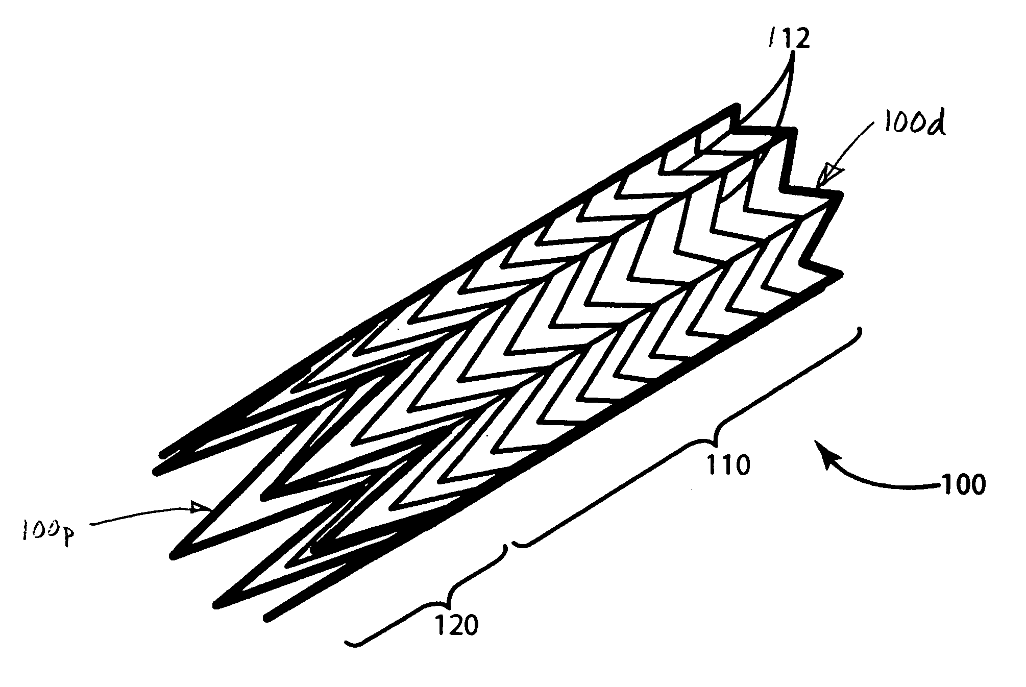
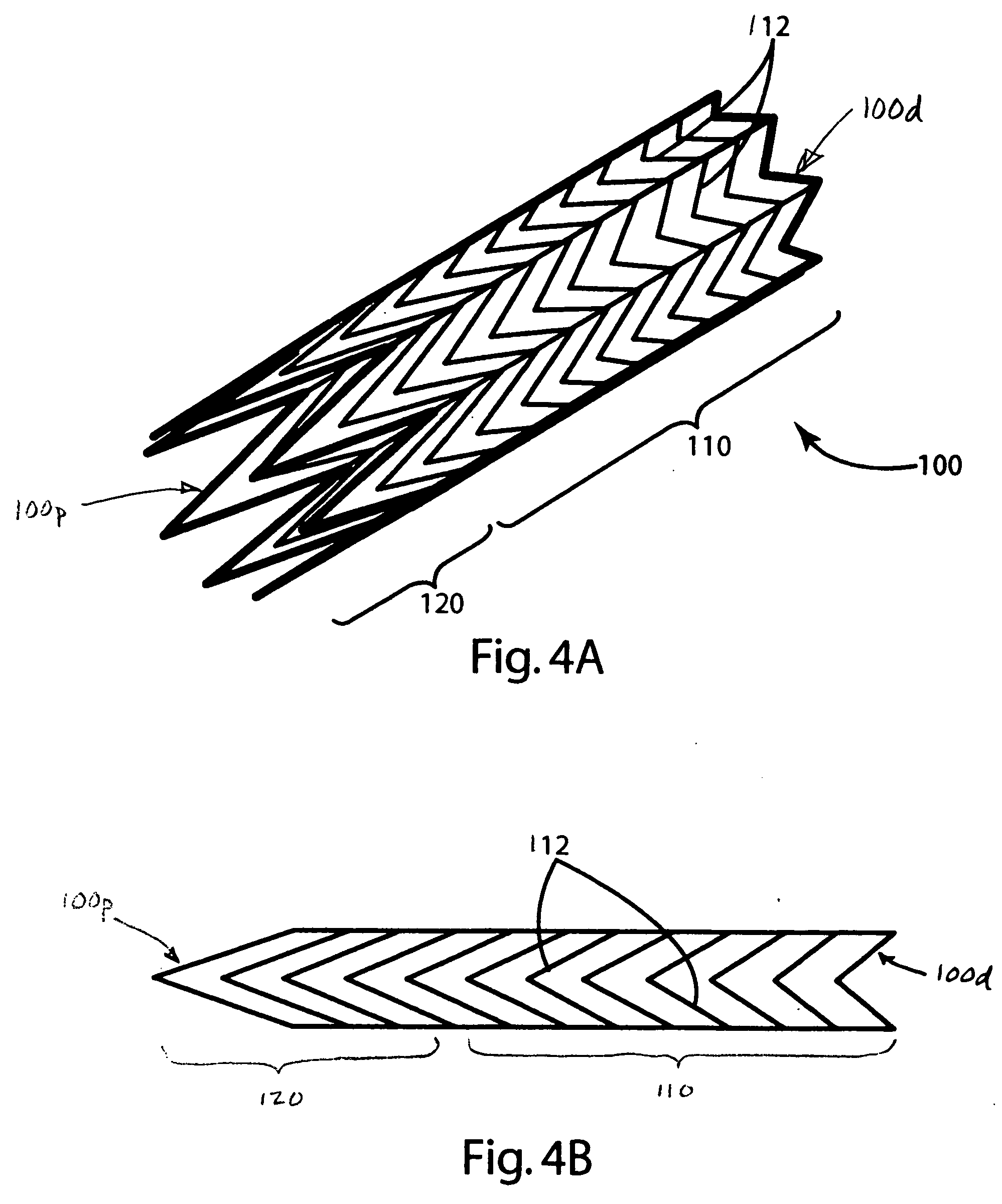
[0043] An ostial stent constructed in accordance with a preferred embodiment of the invention is illustrated in FIGS. 4-8 and generally designated 100. The stent includes a generally distal portion 110 and a generally proximal portion 120.

[0044] The struts 112 in the stent 100 are uniformly spaced along the length of the stent 100. In other words, the distance between any two struts 112 is equal. However, the lengths of the struts 112 vary along the length of the stent 100. The struts are shortest at the extreme distal end 100d, and the struts are longest at the extreme proximal end 100p. In the preferred embodiment, the length of each strut is longer than the strut on one side and shorter than the strut on the other side, so that the length of the struts 112 increases from the extreme distal end 100d to the extreme proximal end 100p.

[0045] Each of the struts is V-shaped. Because the struts vary in length, the Vs form different angles depending on the length of the ...


PUM


Abstract

The specification discloses a cardiovascular ostial stents, a ostial stent balloon, and methods for their use. The stent includes two portions having different degrees of expandability. The distal portion has a normal degree of expandability to support a vessel. The proximal portion has a higher degree of expandability so that it can be formed into a flange-like structure. The balloon is designed to deploy the new stent in a single operation. The balloon includes first and proximal portions having different diameters corresponding to the first and proximal portions of the stent. The distal portion is of normal diameter to deploy the distal portion of the stent in the vessel. The proximal portion is of greater diameter to form the proximal portion of the stent into the flange-like structure. The method involves deploying a conventional stent through one branch of the bifurcation, and then deploying one of the novel stent through a wall of the first stent and into the other branch. The flange-like structure on the novel stent secures the novel stent within the conventional stent. Finally, a one-piece Y-shaped stent is provided for placement in a bifurcated artery.

Description

BACKGROUND OF THE INVENTION [0001] The present invention relates to cardiovascular stents and to methods of using such stents. [0002] Cardiovascular stents are well known and are widely used in cardiovascular procedures. For example, a stent can be inserted into an artery after angioplasty to support the artery in its post-angioplasty size. Wherever used, the stents are delivered to the desired location while mounted on a balloon to facilitate movement through arteries. When the stent is in the desired location, the balloon is inflated to expand the stent and thereby deploy the stent to support the artery. [0003] A prior art stent 10 is illustrated in FIG. 1. The stent 10 includes a plurality of generally V-shaped struts 12 interconnected in a generally tubular configuration. The V-shaped struts are generally closed when the stent is collapsed (e.g. on a balloon), and the V-shaped struts are generally opened when the stent deployed. The spacing, thickness, and strength of the struts...

Claims


Application Information

Patent Timeline
Patent Type & Authority Applications(United States)
IPC IPC(8): A61F2/00A61F2/82
CPCA61F2/856A61F2230/005A61F2/915A61F2/954A61F2/958A61F2002/821A61F2002/91508A61F2002/91516A61F2002/91525A61F2002/91533A61F2002/91558A61F2002/91575A61F2250/0039A61F2250/006A61F2230/0054A61F2/91
Inventor MUSTAPHA, JIHAD A.
Owner SQUAREONE
Why Eureka
Try Eureka