
Router

a technology of routers and wheels, which is applied in the field of routers, can solve problems such as lack of comfort, and achieve the effect of reducing friction and reducing the discomfort of the operator

Inactive Publication Date: 2005-09-01
MILWAUKEE ELECTRIC TOOL CORP
View PDF99 Cites 5 Cited by
  • Summary
  • Abstract
  • Description
  • Claims
  • Application Information

AI Technical Summary

Benefits of technology

[0004] Typically, existing routers include one or more hand grips spaced apart on opposite sides of the housing or the base to control movement of the router on the workpiece. Many operators, however, grip a router by the housing or the base. A typical router is manufactured from hard plastic or metal, which provide minimal friction and lack of comfort to the operator.

Problems solved by technology

A typical router is manufactured from hard plastic or metal, which provide minimal friction and lack of comfort to the operator.

Method used


Image

  • Router
  • Router
  • Router

Examples


Embodiment Construction

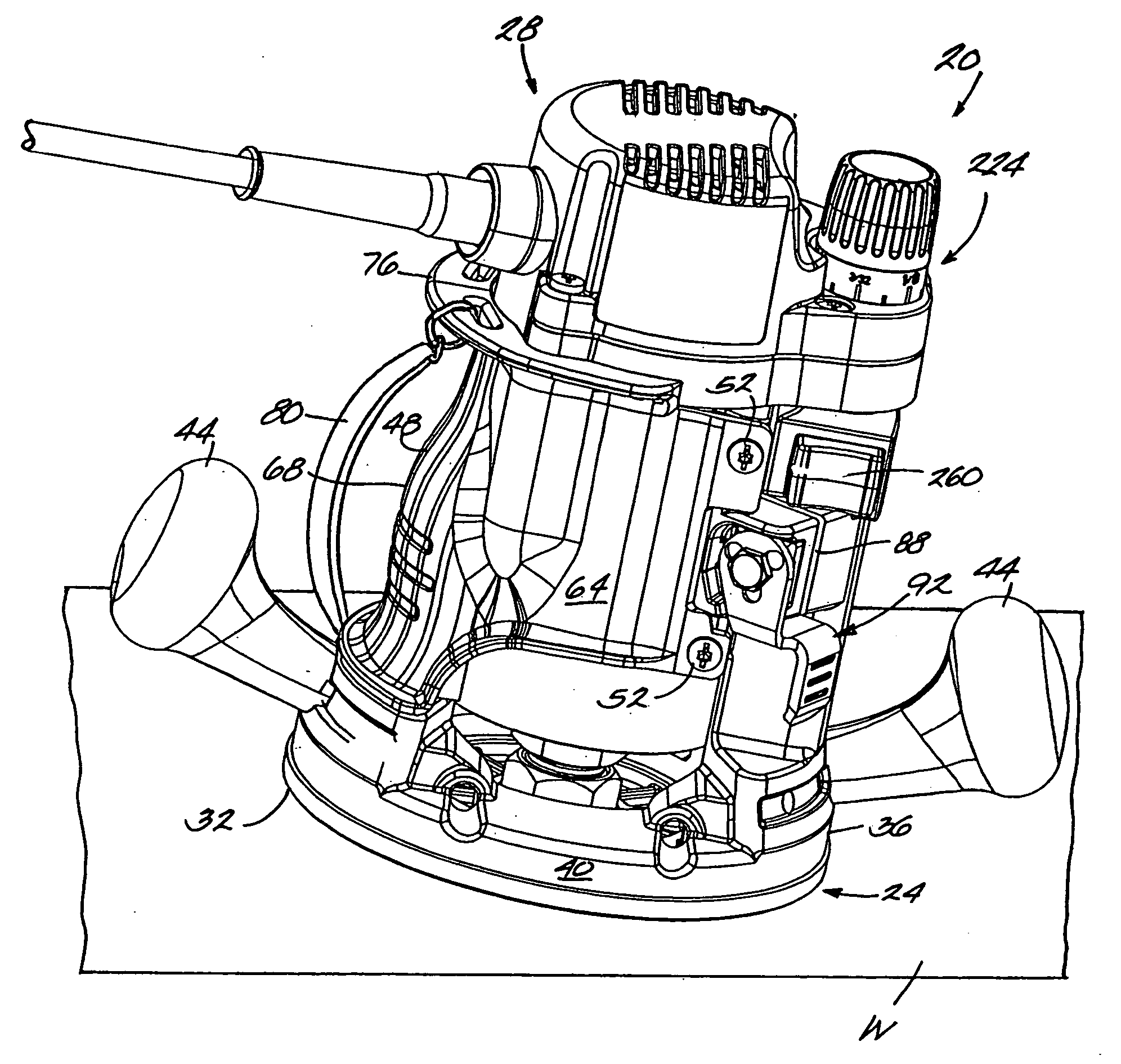
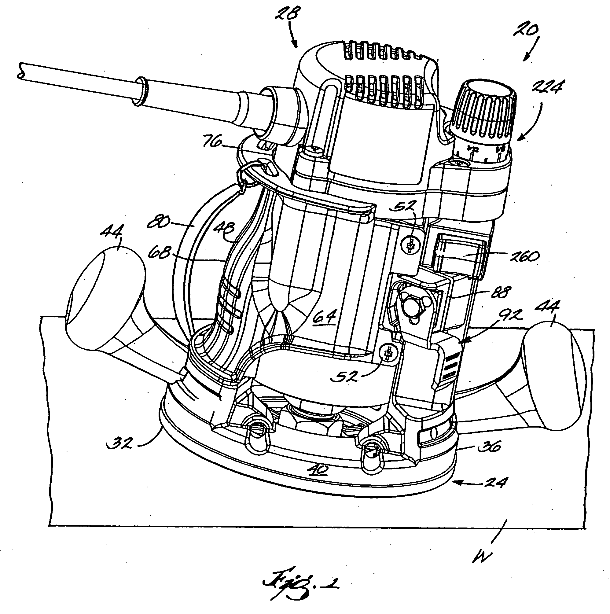
[0031] A hand-held router 20 embodying aspects of the invention is illustrated in FIG. 1. The router 20 includes a base 24 and a motor housing 28 movably supported by the base 24. The housing 28 supports (see FIG. 12) a motor 30 operable to drive a tool element (not shown) to cut a workpiece W. In the illustrated construction, the router 20 is a fixed-base router. However, in other constructions (not shown) and for aspects of the invention, the router 20 may be a plunge router.

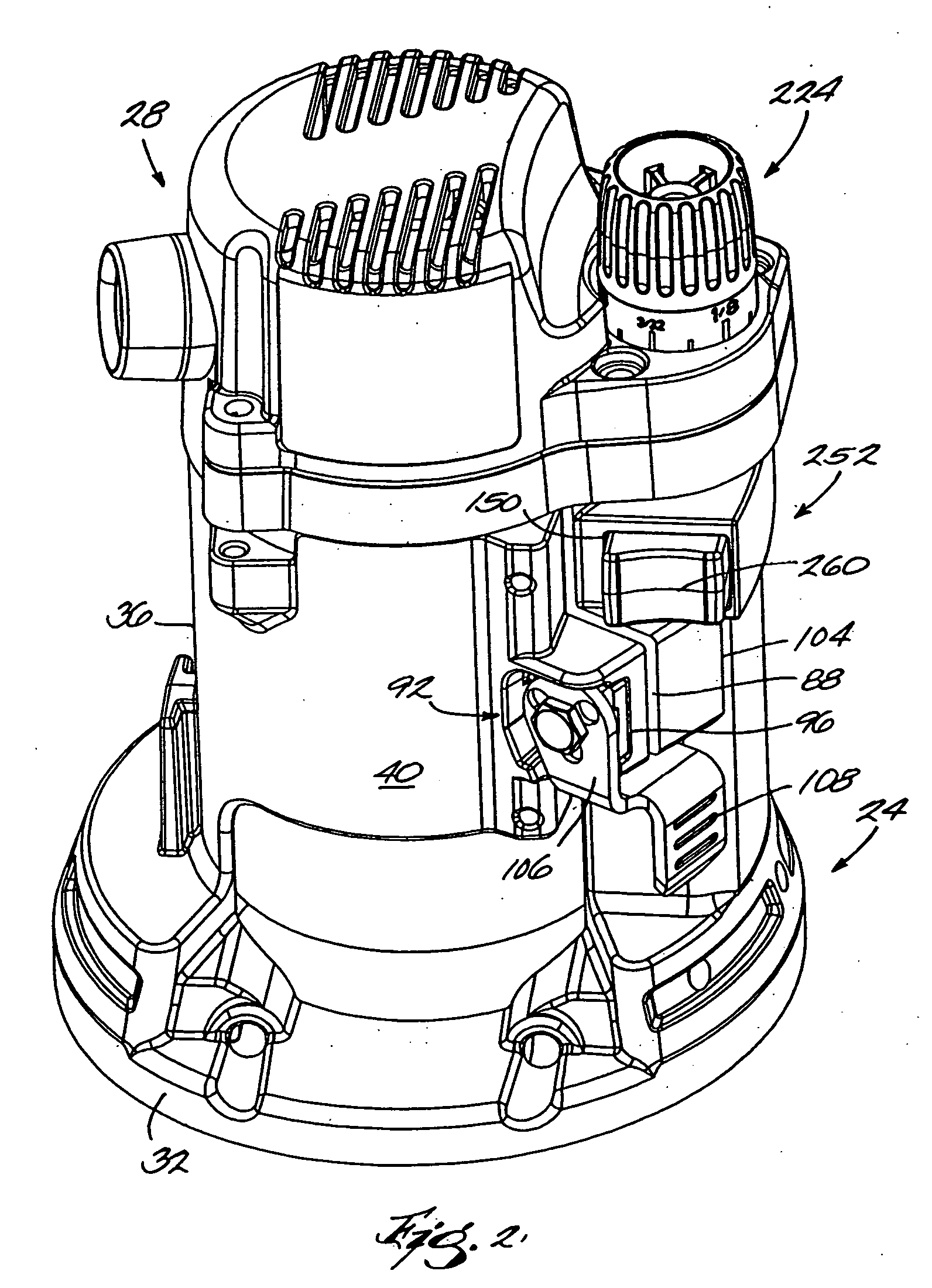
[0032] As shown in FIGS. 1-3, the base 24 includes a sub base or base plate 32 designed to interface with a work surface, such as the surface of the workpiece W. The base 24 also includes a generally cylindrical annular sleeve 36 extending upwardly from the base plate 32. The sleeve 36 is preferably fastened to, but may be formed integrally with the base plate 32 and has a generally cylindrical outer surface 40.

[0033] A pair of knob-like handles 44 removably mountable on the base 24 on opposite sides of the ...


PUM

PropertyMeasurementUnit
angleaaaaaaaaaa
angleaaaaaaaaaa
angleaaaaaaaaaa

Abstract

A power tool, such as, for example a router. In some aspects, a router includes a base, a housing and a hand grip attachable to one of the base and the housing, and the hand grip may be contoured to fit a hand of an operator and may be at least partially formed of an elastomeric material. In some aspects, a router includes a housing and a hand grip connected to the housing. In some aspects, a router is operable above a workpiece and under a table. In some aspects, a router includes a base, a motor housing and an adjustment mechanism supported by at least one of the base and the motor housing for adjusting the position of the motor housing relative to the base. In some aspects, a case for a router includes a base plate operable to support a router with a bit attached to the router.

Description

RELATED APPLICATIONS [0001] This application is a divisional of U.S. application Ser. No. 10 / 831,745, filed Apr. 23, 2004, which is a divisional of U.S. application Ser. No. 10 / 718,048, filed Nov. 19, 2003, which is a continuation of U.S. application Ser. No. 09 / 927,448, filed Aug. 11, 2001, which claims the benefit of U.S. Provisional Application Ser. No. 60 / 224,852 filed Aug. 11, 2000, the entire contents of all are hereby incorporated by reference.FIELD OF THE INVENTION [0002] The invention relates to hand-held power tools and, more particularly, to routers. BACKGROUND OF THE INVENTION [0003] A router generally includes a base for supporting the router on a workpiece surface, a housing supported by the base and movable relative to the base, and a motor supported by the housing and operable to drive a tool element. In a fixed-base router, the housing is fixed or locked in a position relative to the base once the depth of cut of the tool element is set. In a plunge router, the hous...

Claims


Application Information

Patent Timeline
Patent Type & Authority Applications(United States)
IPC IPC(8): B25H3/00B27C5/02B27C5/10
CPCB25F5/003B25H3/006B27C5/02Y10T409/308176Y10T409/307952Y10T409/30924Y10T409/306608B27C5/10
Inventor MCDONALD, RANDYBORCHARDT, DALETHORSON, TROYHESSENBERGER, JEFFREY C.BERG, CHRISTOPHERHOLLY, JEFFREY S.
Owner MILWAUKEE ELECTRIC TOOL CORP
Learn More