Rotation-independent actuation of a machine element

a technology of rotating machine parts and rotating parts, which is applied in the direction of machines/engines, mechanical equipment, manufacturing tools, etc., can solve the problems of undue friction, corresponding wear of seals, and known pneumatically activated chucks that cannot be operated when, so as to reduce wear, reduce friction, and reduce the effect of loss

Inactive Publication Date: 2005-07-05
FORKARDT
View PDF15 Cites 6 Cited by
  • Summary
  • Abstract
  • Description
  • Claims
  • Application Information

AI Technical Summary

Benefits of technology

[0004]The invention is defined as recited in the main claim. This avoids the above drawbacks and brings some additional advantages such as the lack of friction between the chuck and the ring. Thus, neither heat nor wear occur at their interface. Further, the air gap can be made very narrow, which entails a correspondingly small loss of pressure. Due to the narrowness of the air gap, and because of the directed currents therein, dirt can practically not enter the command circuit, which again reduces the wear and is important both for the reliability and for the precision of the machine.

Problems solved by technology

However, the known pneumatically activated chucks can only be operated when they are at rest, because the diaphragm seals used at the interface between the immobile channels delivering compressed air and the channels in the rotating chuck only allow a noticeable increase of air pressure in the chuck without a great pressure loss when the chuck is at rest.
Indeed, if the channels are pressurized when the chuck rotates, this pressure generates an undue friction and a corresponding wear of the seals.
It is moreover impossible to avoid an undesirable soiling of the gaskets, which in turn deteriorates the air tightness of the seals.
However, this arrangement is only feasible for small diameters of the slit because otherwise an excessive pressure loss occurs, and the chuck cannot be operated anymore.
Also, when the chuck is large this arrangement requires a ball bearing with a huge diameter, which brings its own problems, among others because such ball bearings overheat at high rotational speed.
Even in normal use the known solutions can be dangerous when a pressure loss occurs because of a imperfect sealing between the stationary ring and the rotating chuck.
The safety of the machine, for instance with regard to an unintentional opening of the check when machining a workpiece, then rests entirely on the faultless functioning of the return valve, and this also represents a potential danger.
Finally, the diaphragm of gasket rings inserted between the rotating and the immobile sections of the channels are prone to become soiled, which is particularly detrimental on a machine tool.

Method used


Image

  • Rotation-independent actuation of a machine element
  • Rotation-independent actuation of a machine element
  • Rotation-independent actuation of a machine element

Examples


Embodiment Construction

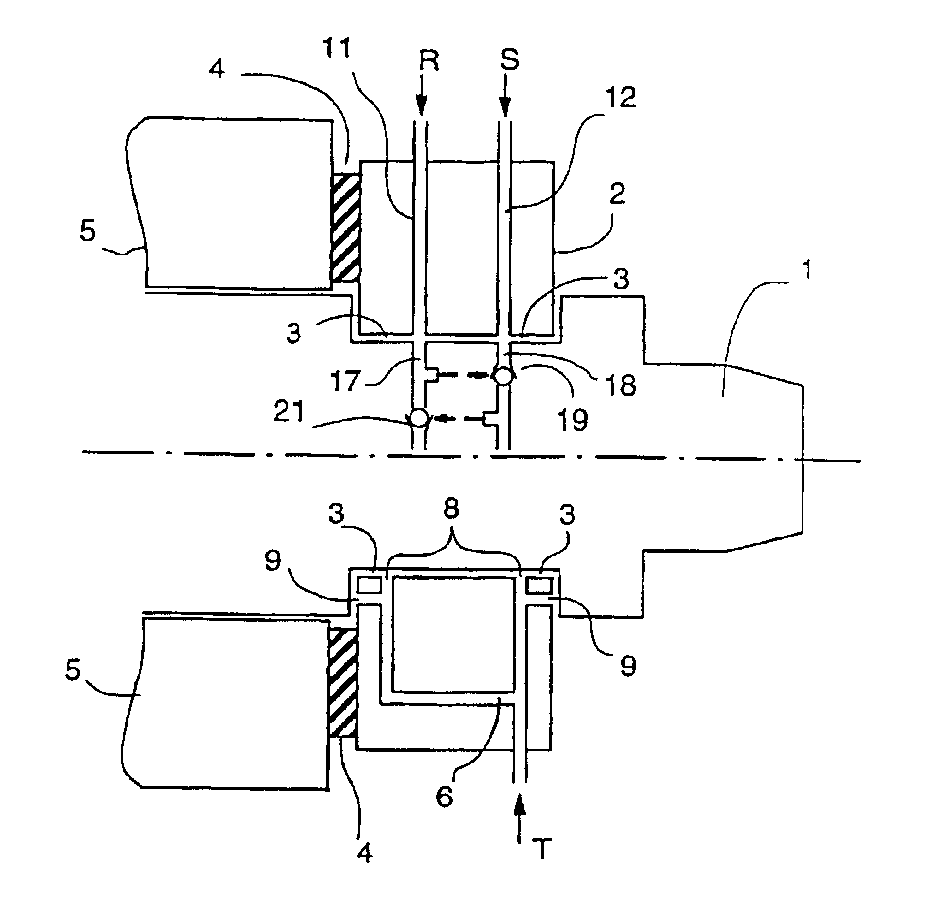
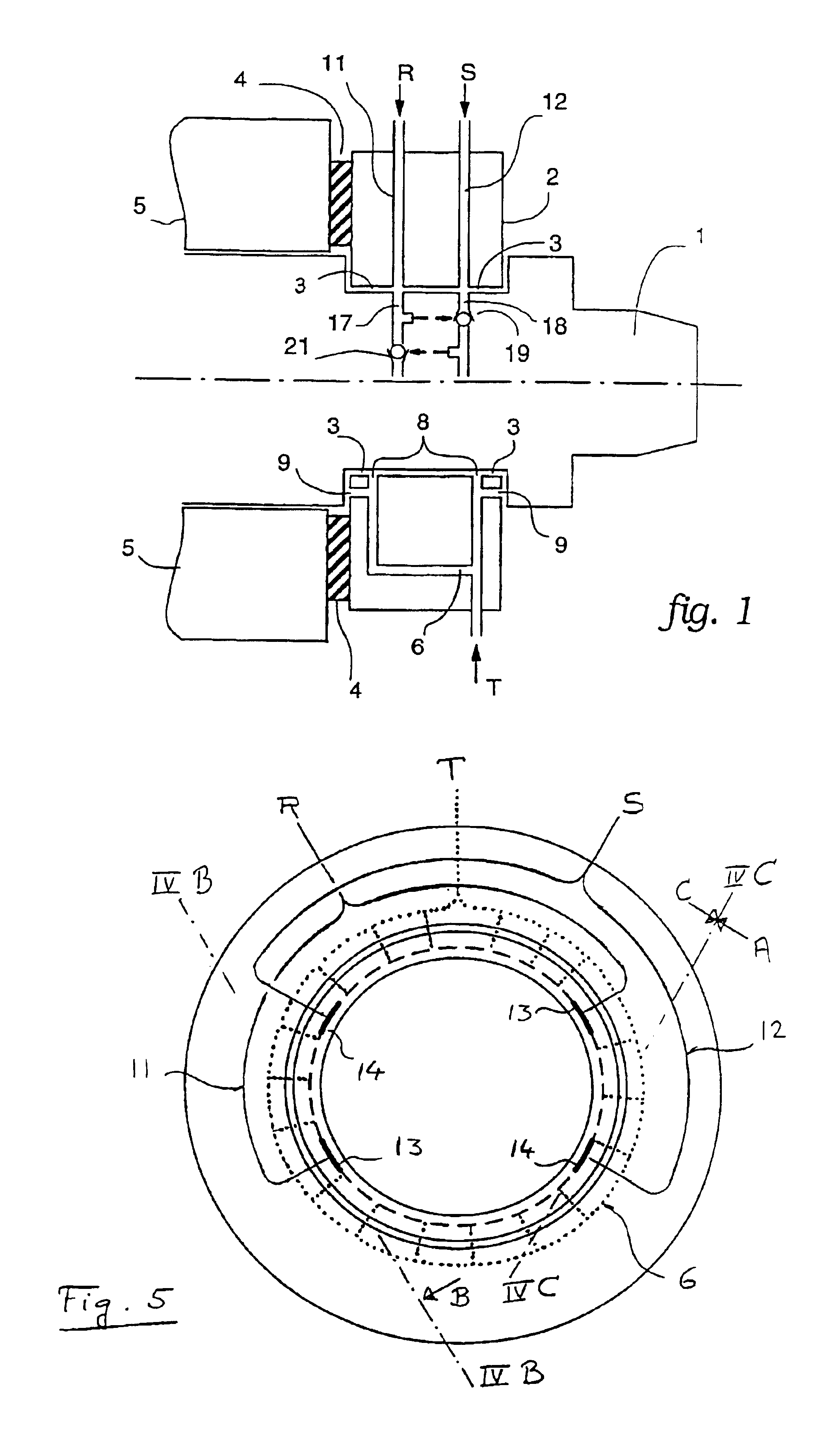
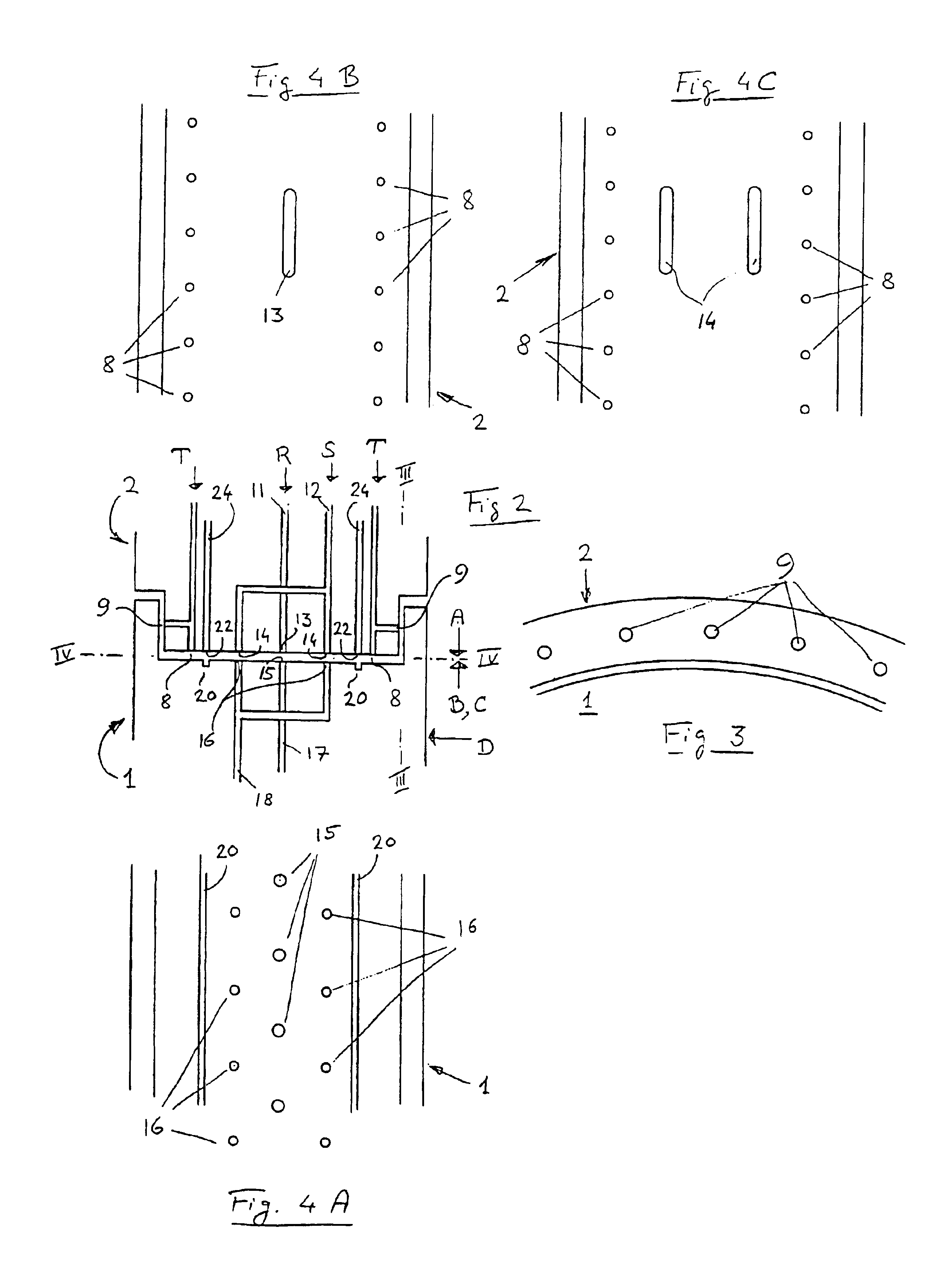
[0012]In order to illustrate the principle of the invention FIG. 1 shows a very schematic section through an embodiment of said invention. Note that the sections shown on either side of the axis are rotated by a certain angle. Reference number 1 designates the pneumatically operated chuck of a machine tool (not shown). A command ring 2 is carried by the body of the chuck and separated from it by two fluid bearings 3. The command ring 2 is attached to an immobile part 5 of the machine tool by means of an elastic holder 4 in a way which permits restricted movements of the ring without however letting it rotate with the chuck 1. A metallic fixation can also be used for the purpose, provided it is built so as to allow the backlash needed in order to avoid a mechanical overdetermination. The compressed air, which will be called “carrier air” hereafter, necessary for operating the fluid bearing 3 enters the channel 6 at the point T, and is then distributed by this channel around the whole...


PUM


Abstract

The invention relates to rotating machine element that contains a mechanism actuated by a fluid pressure. The aim of the invention is to allow for a supply of actuation fluid also during the rotation. To this end, a non-rotating control element (2) is mounted on two fluid bearings (3) on the machine element, said bearings being spaced apart in the axial direction and allowing flows of actuation fluid to flow from one element to the other. Feed lines (R, S) in the control element are provided with a series of radially inwards facing ports (13, 14) and reception channels (17, 18) in the machine element, a series of radially outward facing orifices (15, 16) being disposed in such a manner that in every relative position both elements for every individual flow of actuation fluid are disposed such that at least one port (13, 14) is aligned with one associated orifice (15, 16).

Description

CROSS-REFERENCE TO RELATED APPLICATIONS[0001]This application claims the priority of the European Patent application 00 105 927.8, which was filed Mar. 23, 2000 and the whole content of which is incorporated herein by reference.BACKGROUND OF THE INVENTION[0002]The invention relates to a method and a device for operating a rotating machine part which can be actuated by a fluid, for instance the so called front-end chuck of a machine tool. It is known to actuate the opening and / or closing of a chuck—both of which will hereafter be called “operating it”—by pneumatic or hydraulic means, which is particularly advantageous for serially machining workpieces. Because of the required and ever increasing machining speed, it is desirable to be able to command the operation of the chuck not only when it is at rest, but also when its rotation has already begun or not yet stopped.STATE OF THE ART[0003]However, the known pneumatically activated chucks can only be operated when they are at rest, be...

Claims


Application Information

Patent Timeline
Patent Type & Authority Patents(United States)
IPC IPC(8): B23B31/30B23B31/02
CPCB23B31/302Y10T279/1274Y10T279/1291
Inventor BOHLER, ERWIN
Owner FORKARDT
Why Eureka
Try Eureka