Drill stem connection

a threaded connection and drill stem technology, applied in the direction of hose connection, screw threaded joint, borehole/well accessories, etc., can solve the problems of long counterbore section prone to buckle outward under high torque, early failure, downhole failure, etc., and achieve the effect of improving yield torque characteristics

Active Publication Date: 2005-09-01
VALLOUREC OIL & GAS FRANCE SAS
View PDF12 Cites 71 Cited by
  • Summary
  • Abstract
  • Description
  • Claims
  • Application Information

AI Technical Summary

Benefits of technology

[0019] A primary object of the invention is to provide a drill stem connection, in particular for a drill pipe tool joint with enhanced yield torque characteristics.
[0020] Another object of the invention is to provide a drill pipe tool joint with enhanced yield torque characteristics while simultaneously having a make-up turns characteristic of a conventional API tool joint.

Problems solved by technology

Leakage out of the tool joints causes wear due to the abrasiveness of the drilling fluid, which can lead to early failure.
The additional make-up torque imparts higher stresses in the connection which may exceed the yield strength of the pin and box and cause downhole failure.
However, the long counterbore section tends to buckle outward under high torque.
Having the internal shoulder contact before the external shoulder creates a risk that the external shoulder may not be sufficiently loaded to effect a seal.
However, drill pipe joints with shallow thread tapers require substantially more rotations of the pin with the box during make up, as compared to conventional API tool joints.
The additional rig time required to make-up these connections is very expensive and undesirable.
The shallow taper also makes connection stabbing and unstabbing more difficult, because the connection must be carefully aligned to avoid thread interference and galling.
Further, the shallow taper requires a large loss of the limited tool joint length when the connection is re-machined after wear or damage.
The prior art joints also provide conventional thread form designs which inhibit optimum yield torque characteristics for pipe joints generally and in particular for double shoulder drill pipe joints.
As the thread taper is reduced, the wedging action gets worse.
Forcing the threads past wedging of the thread crests can eventually lead to galling and other damage.

Method used


Image

  • Drill stem connection
  • Drill stem connection
  • Drill stem connection

Examples


Embodiment Construction

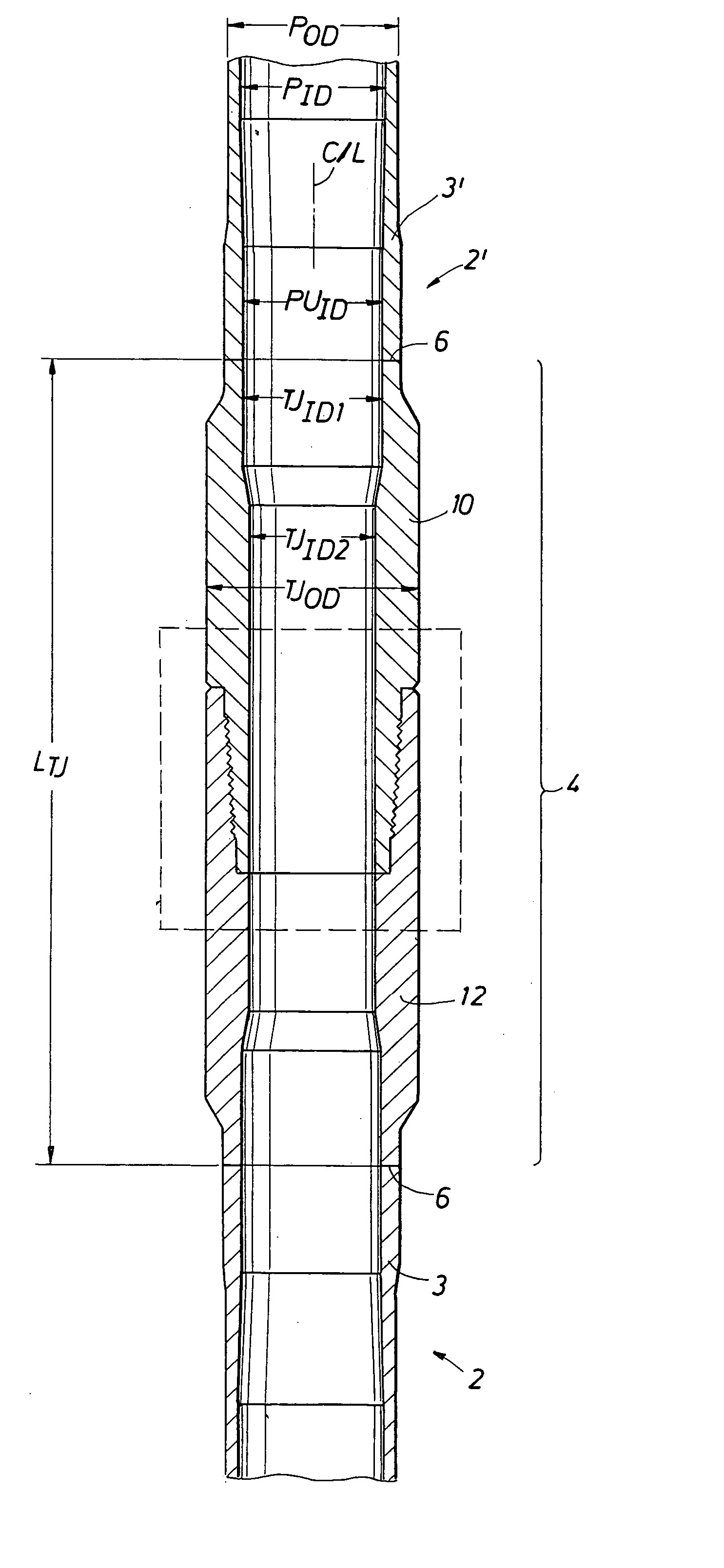
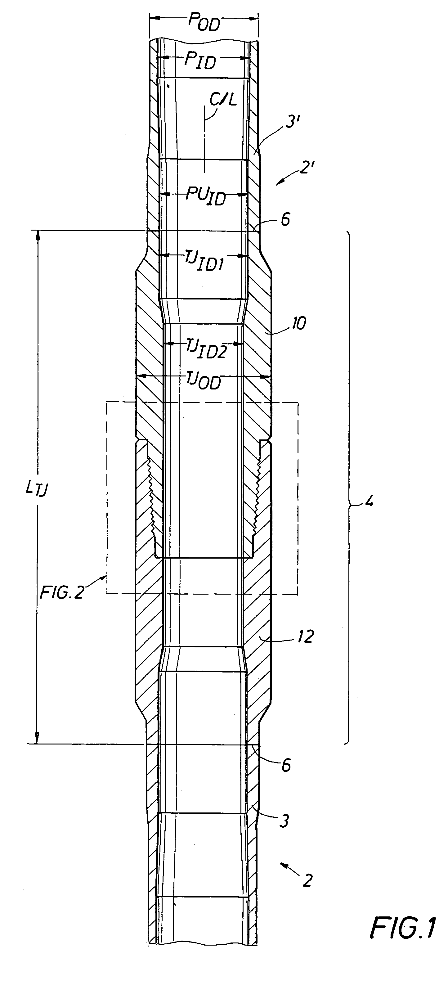
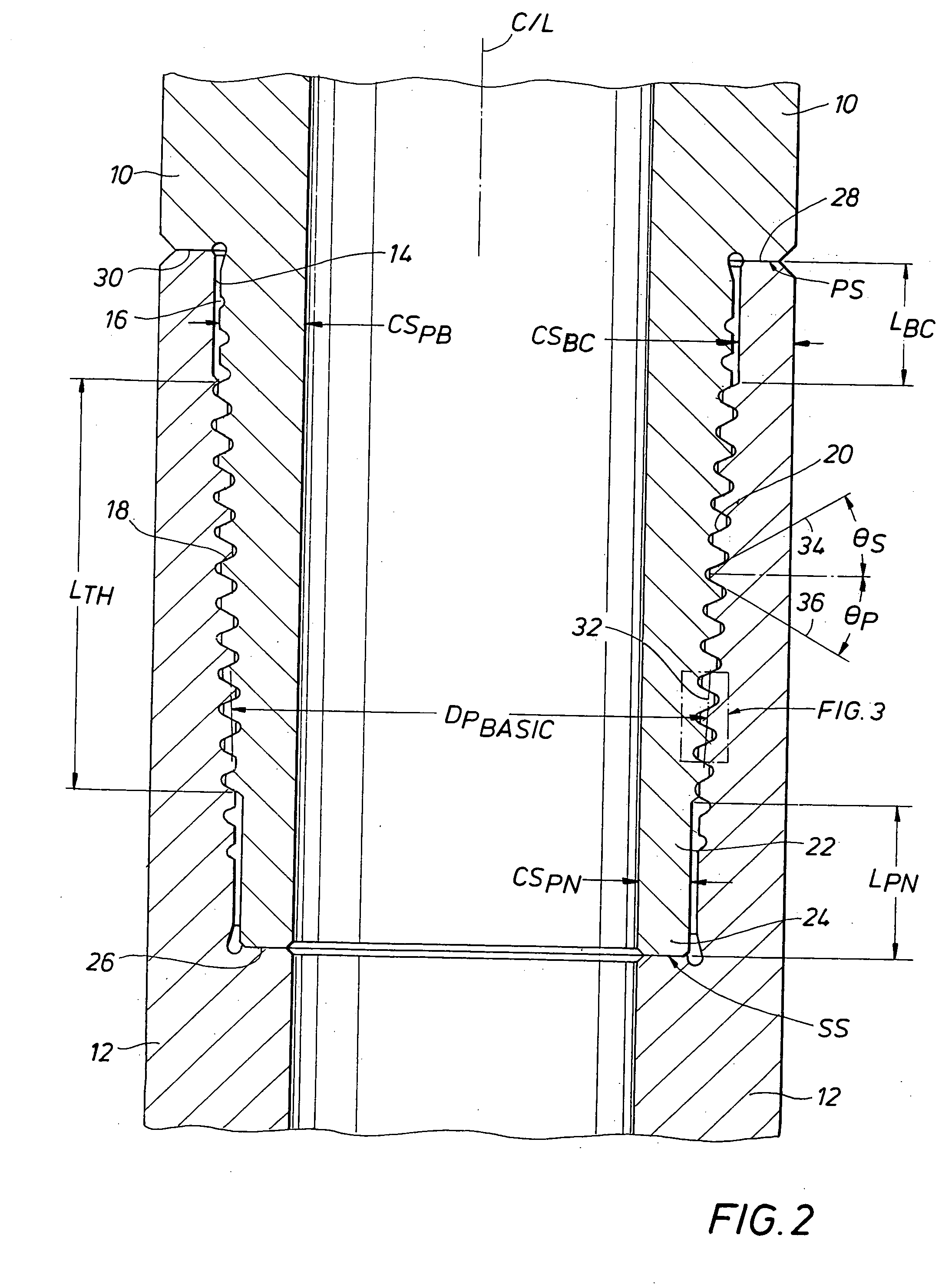
[0048] The description below describes the preferred embodiments by reference to the attached figures which include reference numbers to parts of the tool string and tool joint of the invention. Correspondence between reference numbers and parts follows:

ReferenceNumberDescriptionPODPipe Outer DiameterPIDPipe Inner DiameterC / LCenter line of joined pipe and tool jointPUIDPipe Upset Inner DiameterTJID1Tool Joint Inner Diameter at weld end ofjointTJID2Tool Joint Inner Diameter at a middle portionof jointTJODTool Joint Outer DiameterLTJTool Joint Length 2Lower Drill Pipe 2′Upper Drill Pipe 3Upset portion of lower drill pipe 3′Upset portion of upper drill pipe 4Tool Joint 6Lower Weld 6′Upper Weld10Pin12Box14Box counterbore16Pin Base18External Tapered Pin Threads20Internal Tapered Box Threads22Pin Nose24Box Internal Shoulder26Pin Face or Circular Rim28Box External Shoulder or Box Face orCircular Rim30Pin External Shoulder32Pitch Line of Threads34Stab Flank of Threads36Pressure or Load Fl...


PUM


Abstract

A double shoulder drill stem connection for high torque applications includes a thread taper within a range between about 1.0 and 1.2 inch per foot. The thread form is characterized by a stab angle between about 35 and 42 and a load angle between about 25 and 34 degrees and by a short thread height with elliptical roots and with crests having an angle which slopes in an opposite direction with respect to the joint centerline from the thread taper. A drill string includes a tool joint having different inner diameters for a substantial axial length to provide enhanced strength in the threaded portion of the joint.

Description

BACKGROUND OF THE INVENTION [0001] 1. Field of the Invention [0002] This invention concerns drill stem threaded connections in general. In particular the invention is for a tool joint and a resulting drill string where the tool joint connects drill pipe sections and other elements of the drill stem together from the surface to the drill bit. Still more particularly, this invention is for a tool joint having internal and external make-up shoulders for high torque application of rotary drilling. [0003] 2. Description of Prior Art [0004] Deep wells such as for oil and gas are drilled with a rotary drill bit rotated by a drill stem which consists of a bottomhole assembly, a string of drill pipe, a kelly or top drive, and all associated equipment in the rotating string to the drill bit. The drill pipe string is made-up of individual members, each about 30 feet in length. The drill pipe members are secured together by a threaded connection, called a tool joint, typically about 1½ feet lon...

Claims


Application Information

Patent Timeline
Patent Type & Authority Applications(United States)
IPC IPC(8): E21B17/042E21B17/20F16L15/06
CPCE21B17/042
Inventor WILLIAMSON, JOSEPH STEPHENGRANGER, SCOTT L.CHANCEY, ROGER D.
Owner VALLOUREC OIL & GAS FRANCE SAS
Why Eureka
Try Eureka