Bottom pole structure with back-side steps

a bottom pole structure and back-side step technology, applied in the field of magnetic write heads, can solve the problems of frequent erasure of adjacent tracks, severe excess saturation of the head,

Inactive Publication Date: 2005-09-01
HEADWAY TECH INC
View PDF6 Cites 3 Cited by
  • Summary
  • Abstract
  • Description
  • Claims
  • Application Information

AI Technical Summary

Benefits of technology

[0010] Another object of at least one embodiment of the present invention has been that said write head be able to tolerate severe excess saturation without causing any adjacent track erasure.

Problems solved by technology

This often brings about severe excess saturation of the head and, as a result, adjacent track erasures often occur.

Method used


Image

  • Bottom pole structure with back-side steps
  • Bottom pole structure with back-side steps
  • Bottom pole structure with back-side steps

Examples


first embodiment

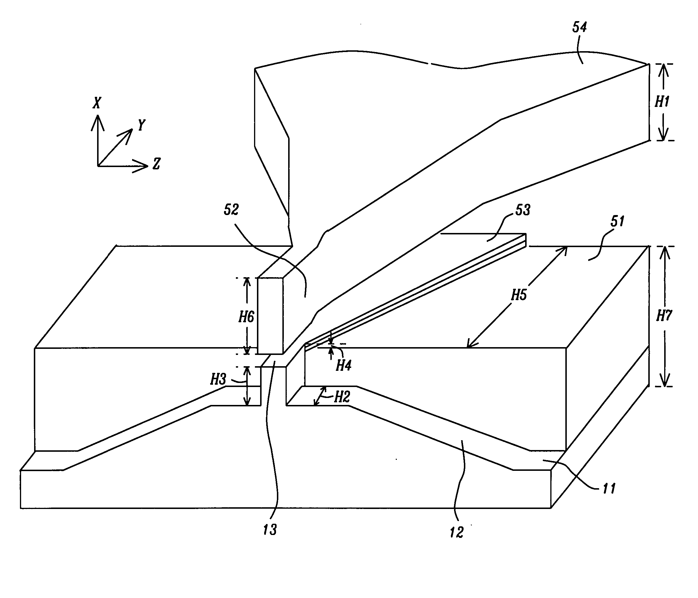
[0023] Returning now to FIG. 5, we continue our description of the invention. The bottom pole has been divided into front and rear sections with a step between them. The front section comprises the sub-structures 11 and 12 along with flux concentrator 13. The rear section (to which the front section is attached) is rectangular prism 51 whose top surface is higher than the top flat portion of element 12 (from which concentrator 13 upwardly extends). The top surface of concentrator 13 is higher than that of prism 51 and, furthermore, flux extender 53 runs from the inside edge of 51 all the way to the back edge of 51. So, as one moves through the write gap, away from the ABS, there is a decrease in the reluctance between the top and bottom poles, except in the write gap region itself. As a result, excess flux generated by higher write currents can be absorbed by the flux extender instead of being diverted to the side of the write gap.

[0024] The key dimensions that determine the perform...

2nd embodiment

2nd Embodiment

[0031] This is illustrated in FIG. 9. This structure is similar to the first embodiment except that there is no end piece (element 52 in FIG. 5). The key dimensions that determine the performance of the device seen in FIG. 9 are as follows:

[0032] Top pole thickness (H1)—between about 0.7 and 2 microns; thickness separating the trapezoidal walls of element 12 (H2)—between about 0.3 and 1 microns; flux concentrator thickness (H3)—between about 0.1 and 0.4 microns; flux extender thickness (H4)—less than about 0.3 microns; distance flux extender extends from the flux concentrator (H5)—between about 0.5 and 2 microns; and height of rectangular prism (H7)—between about 2 and 4.5 microns.

3rd embodiment

3rd Embodiment

[0033] This is illustrated in FIG. 10. This structure is similar to the second embodiment except that rectangular prism 99 does not extend all the way to the outer edge of flat layer 11. The key dimensions that determine the performance of the device seen in FIG. 9 are as follows:

[0034] Top pole thickness (H1)—between about 0.7 and 2 microns; thickness separating the trapezoidal walls of element 12 (H2)—between about 0.3 and 1 microns; flux concentrator thickness (H3)—between about 0.1 and 0.4 microns; flux extender thickness (H4)—less than about 0.3 microns; distance flux extender extends from the flux concentrator (H5)—between about 0.5 and 1.5 microns; and height of rectangular prism (H7)—between about 2 and 4.5 microns.


PUM

PropertyMeasurementUnit
thicknessaaaaaaaaaa
thicknessaaaaaaaaaa
thicknessaaaaaaaaaa

Abstract

To generate a high data transfer rate from a magnetic write head, a faster flux rise time is needed. This often brings about severe excess saturation of the head and, as a result, adjacent track erasures often occur. This problem has been overcome by dividing the bottom pole into front and rear sections with a step between them. The write gap is part of the front section while the rear section (to which the front section is attached) is closer to the top pole so excess flux generated by higher write currents can be absorbed in a direction normal to the ABS instead of being diverted to the bottom pole shoulder.

Description

FIELD OF THE INVENTION [0001] The invention relates to the general field of magnetic write heads with particular reference to improving track density. BACKGROUND OF THE INVENTION [0002] To enable increases in the recording density achieved by a magnetic head, the coercivity of the recording media must be increased to overcome the demagnetization field of the magnetic transition. However as the track width decreases, so does the head field. When a high-end hard disk drive (HDD) generates a high data transfer rate, in the order of 1 Gbit / s, or more, not only is greater head field strength required, but there also is a need for a faster flux rise time. In order to achieve a large enough overwrite value, even in such high frequency conditions, the write current is boosted, giving its waveform a large overshoot. This often brings about severe excess saturation of the head and, as a result, adjacent track erasures often occur. [0003]FIG. 1 is a schematic illustration of a conventional pla...

Claims


Application Information

Patent Timeline
Patent Type & Authority Applications(United States)
IPC IPC(8): G11B5/31G11B5/127G11B5/147
CPCG11B5/1274
Inventor TAKANO, KENICHIDOVEK, MORIS
Owner HEADWAY TECH INC
Why Eureka
Try Eureka