Method and system for determining a location of a wind-powered electrical energy facility

a technology of wind power and electrical energy, applied in the direction of instruments, process and machine control, material dimension control, etc., can solve problems such as partial views

Inactive Publication Date: 2005-09-01
EXELON WIND LLC
View PDF12 Cites 18 Cited by
  • Summary
  • Abstract
  • Description
  • Claims
  • Application Information

AI Technical Summary

Benefits of technology

[0004] A method for determining a location of a conversion device for converting wind energy into electrical energy comprises establishing a plurality of data layers, including at least a wind data layer and a transmission grid data layer. Each data layer contains attribute data that is associated with corresponding location data. The location data of one layer is aligned with the location data of other layers to form a composite layer. The composite layer is searched to identify the first compliant location data associated with a target value or a target value range of the attribute data for the wind data layer. The composite layer is searched to identify a second compliant location data associated with a target value or a target value range of the attribute data for the transmission grid data. The composite layer is searched to identify a third compliant location data associated with a target value or target value range of the attribute data for an additional data layer other than the wind data layer and the transmission grid data layer. The intersection of the first compliant location data, the second compliant location data, and the third compliant data is determined. The intersection is identified as one or more preferential regions for locating an energy conversion device.

Problems solved by technology

However, the engineering models provide only a partial view of reality because other critical financial, geostatistical, and other information may influence the economic viability of a wind farm.

Method used


Image

  • Method and system for determining a location of a wind-powered electrical energy facility
  • Method and system for determining a location of a wind-powered electrical energy facility
  • Method and system for determining a location of a wind-powered electrical energy facility

Examples


Embodiment Construction

[0022] As used herein, the terms “transmission” and “distribution”, and variations thereof, do not refer to and are not limited to any particular voltage range or ranges. The terms transmission and distribution shall be accorded their ordinary dictionary definitions when used as nouns or adjectives. Notwithstanding the foregoing, to clarify the definitions commonly used in utility industry within the United States, “transmission voltage range” refers to above approximately 161 kilovolts; “sub-transmission voltage range” refers to approximately 55 kilovolts to 138 kilovolts; and “distribution voltage range” refers to approximately 33 kilovolts and below.

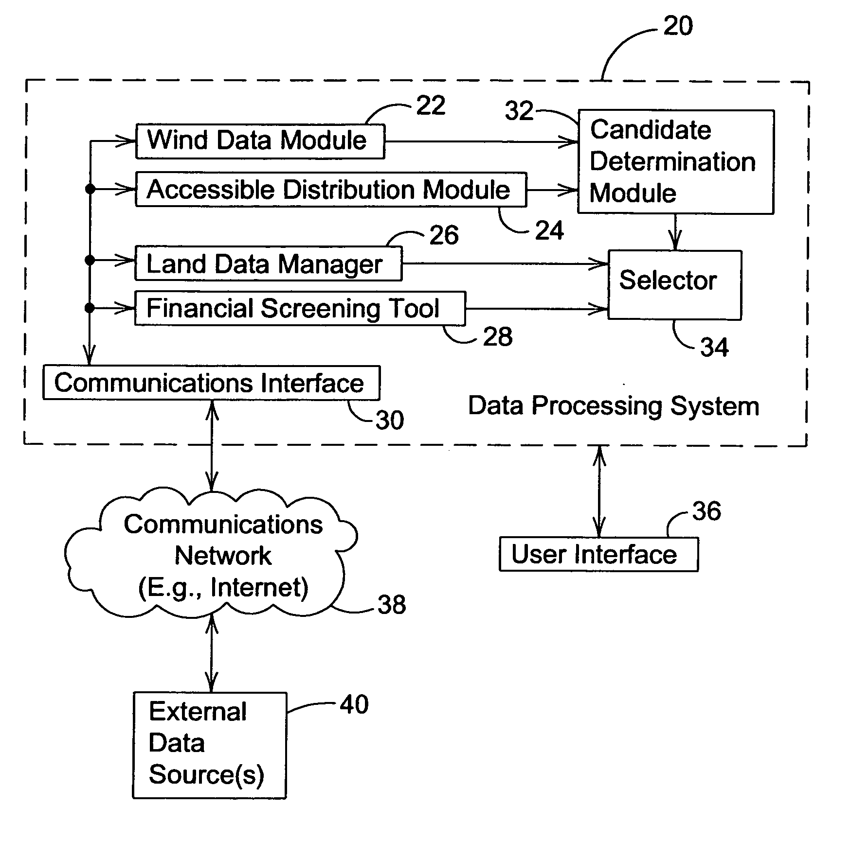
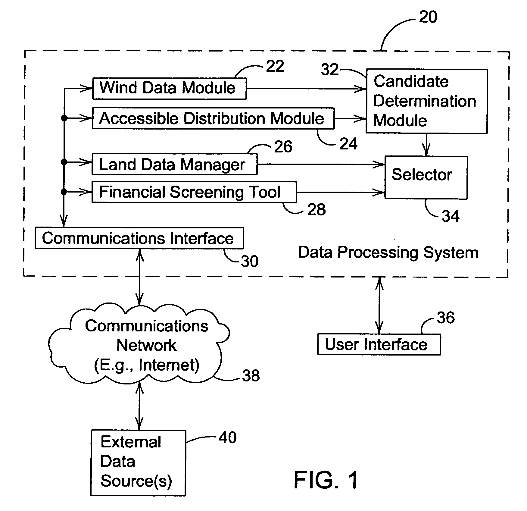
[0023]FIG. 1 is a block diagram of a system for establishing a wind-powered generation facility. The data processing system 20 is associated with a user interface 36 for accepting input data from a user and for providing output data to a user. The data processing system 20 may communicate via a communications network 38 (e.g., Intern...


PUM


Abstract

A method for determining a location of a conversion device for converting wind energy into electrical energy comprises establishing a plurality of data layers, including at least a wind data layer and a transmission grid data layer. Each data layer contains attribute data that is associated with corresponding location data. The location data of one layer is aligned with the location data of other layers to form a composite layer. The composite layer is searched to identify the first compliant location data associated with a target value or a target value range of the attribute data for the wind data layer. The composite layer is searched to identify a second compliant location data associated with a target value or a target value range of the attribute data for the transmission grid data. The composite layer is searched to identify a third compliant location data associated with a target value or target value range of the attribute data for an additional data layer other than the wind data layer and the transmission grid data layer. The intersection of the first compliant location data, the second compliant location data, and the third compliant data is determined. The intersection is identified as one or more preferential regions for locating an energy conversion device.

Description

[0001] This document claims priority based on U.S. provisional application Ser. No. 60 / 548,298, filed Feb. 27, 2004, and entitled METHOD AND SYSTEM OF ESTABLISHING A WIND-POWERED ELECTRICAL GENERATION FACILITY, under 35 U.S.C. 119(e).FIELD OF THE INVENTION [0002] This invention relates to a method and system for determining a location of a wind-powered electrical energy facility. BACKGROUND OF THE INVENTION [0003] In the prior art, certain engineering models have been used to establish technical viability in planning the location of wind turbines or wind farms. The engineering models may consider the topography of a region, the wind regime of the region, and the technical specifications of various commercially available wind turbines. However, the engineering models provide only a partial view of reality because other critical financial, geostatistical, and other information may influence the economic viability of a wind farm. Thus, a need exists for an accurate model to plan an eco...

Claims


Application Information

Patent Timeline
Patent Type & Authority Applications(United States)
IPC IPC(8): G06F17/50
CPCG06F30/00
Inventor MERTINS, KARL-HEINZFULKERSON, WILLIAMHALTERMAN, JERRYMUEHLBACH, GEORGEJOSHI, DEEPAK
Owner EXELON WIND LLC
Why Eureka
Try Eureka