Waste disposal device including a rotatable geared rim to operate a cartridge
Inactive Publication Date: 2005-09-08
ANGELCARE USA LLC
View PDF83 Cites 52 Cited by
Summary
Abstract
Description
Claims
Application Information
AI Technical Summary
This helps you quickly interpret patents by identifying the three key elements:
Problems solved by technology
Method used
Benefits of technology
Benefits of technology
[0039] To allow for easy removal of the series of encapsulated waste packages from the container, a pail, or another comparable removable waste receptacle, may be placed in the container on a base for receiving the encapsulated waste packages and an access door is formed in an outer wall of the container to enable removal and emptying of the pail. The pail may be lined with a trash bag so that when the pail is removed, the trash bag
Problems solved by technology
A twist rim is rotatably coupled to the cartridge such that rotation of the twist rim causes twisting of the tubing.
A major inconvenience of diaper pails of the “Diaper Genie”™ type is that it is necessary to manually tie both ends of the tubing to use the diaper pail.
The necessary, multiple tyings of the tubing is bothersome and moreover, when the knots are not made sufficiently strong, unpleasant odors emanating from the waste packages can escape through the knots.
Another problem with diaper pails of the “Diaper Genie”™ type is that cutting the tubing is difficult and requires the use of a manually operable cutting instrument.
This cutting instrument does not enable easy cutting of the tubing.
Yet another problem with diaper pails of the “Diaper Genie”™ type is that the series of waste packages are removed from the diaper pail through an access door pivotally connected to the bottom end of the container.
The series of wa
Method used
Image
Click on the blue label to locate the original text in one second.
Reading with bidirectional positioning of images and text.
Examples
first embodiment
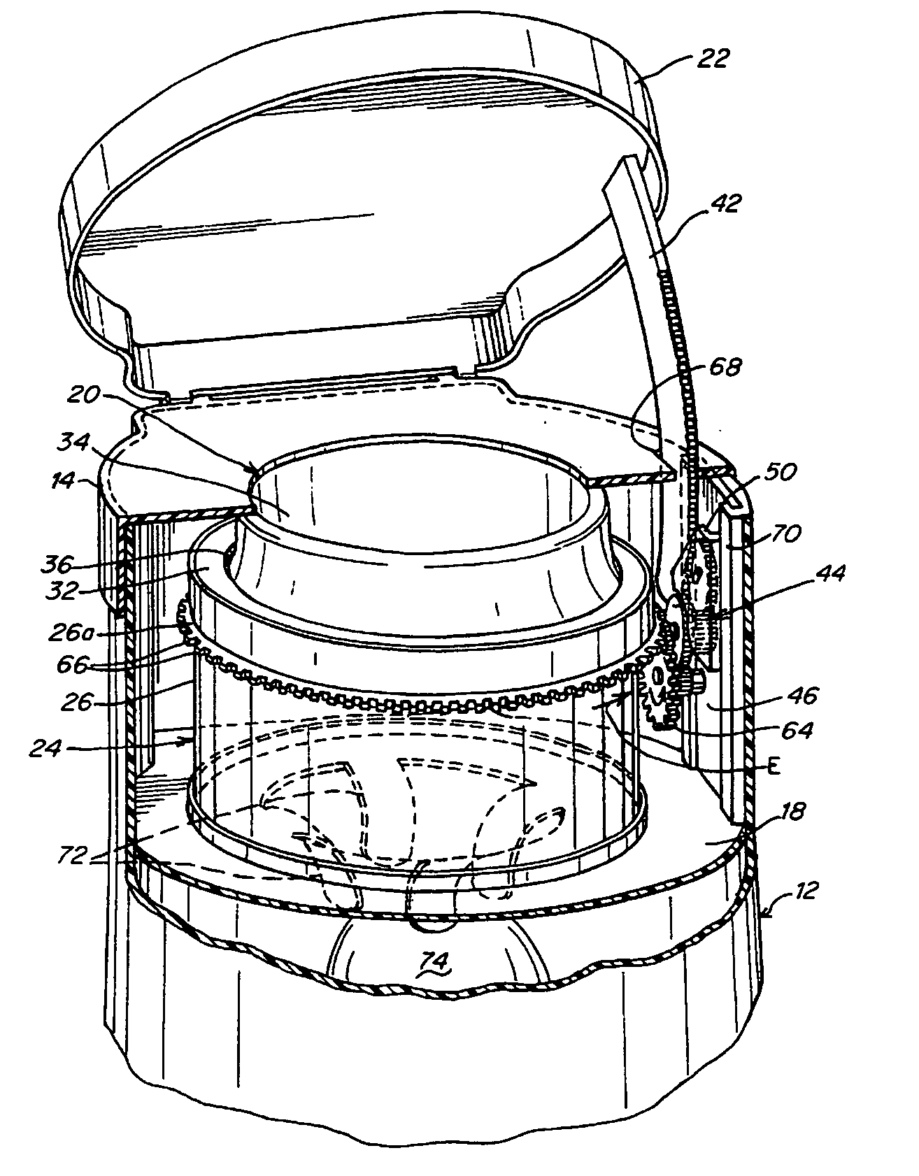
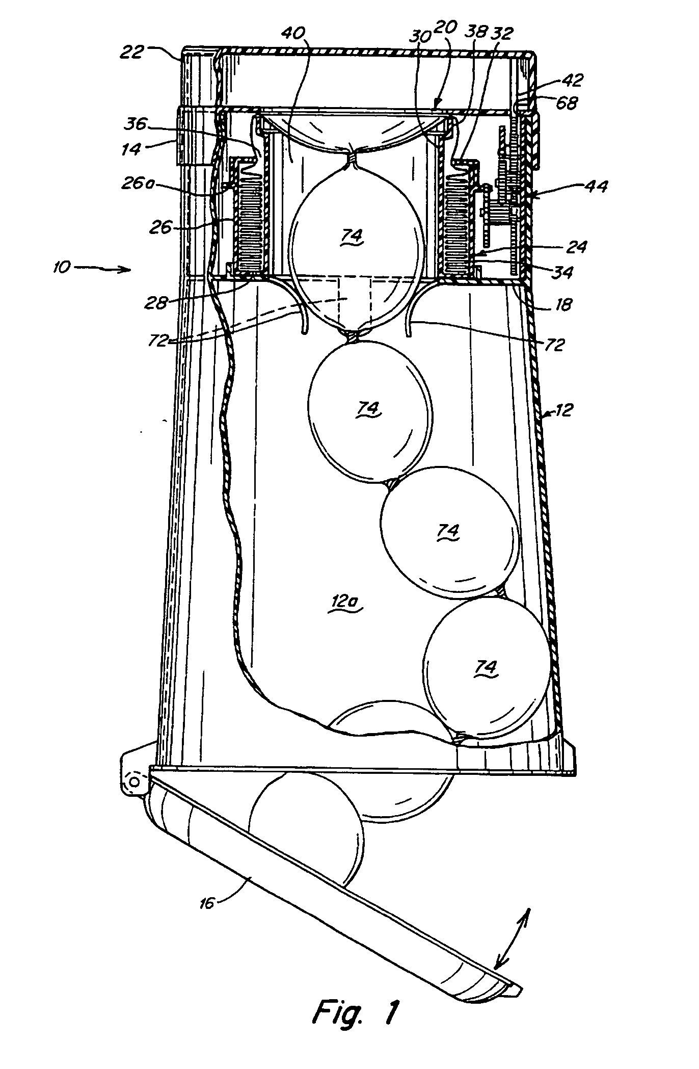
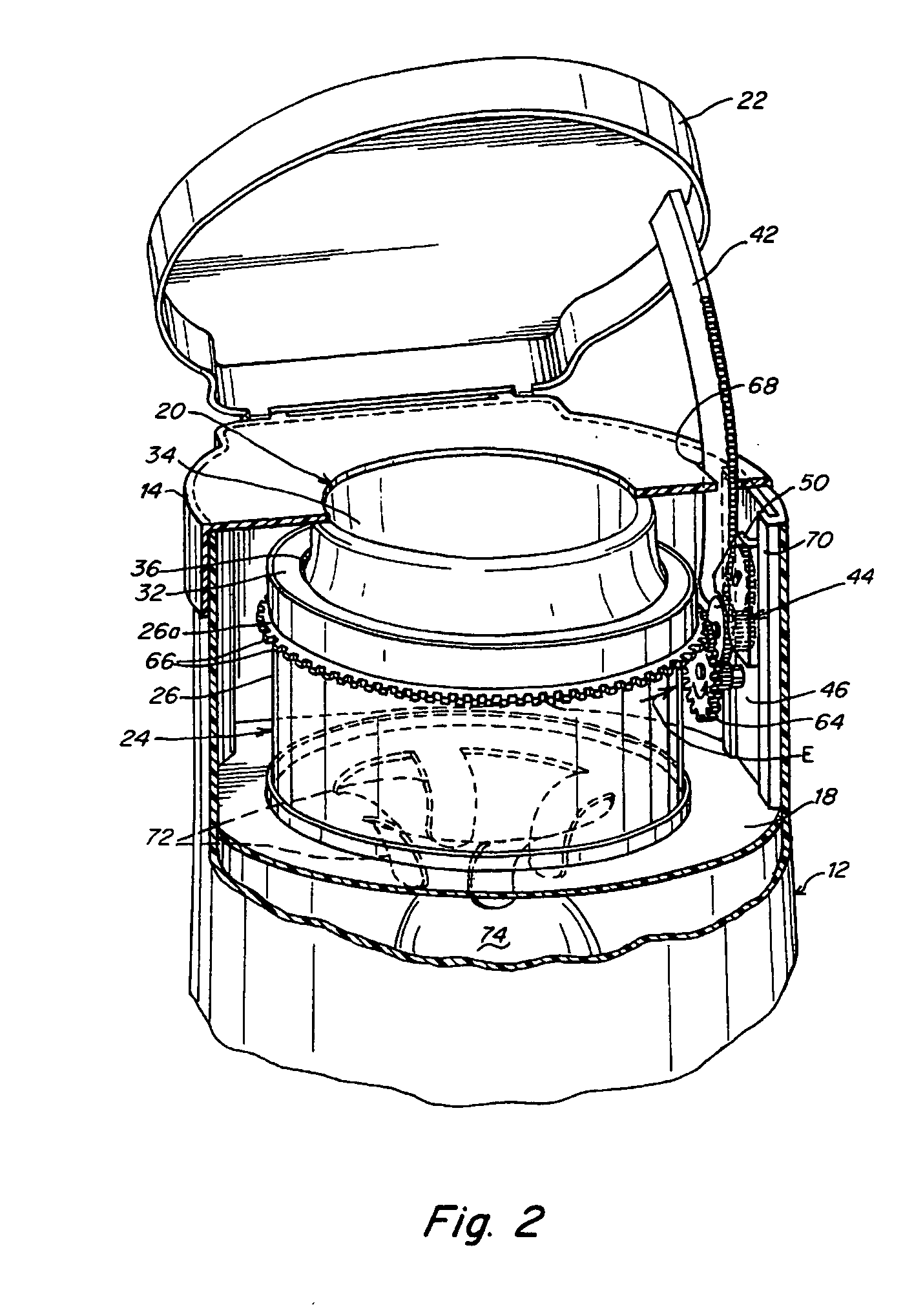
[0129] such a waste disposal device is shown in FIGS. 7-9 and it incorporates a rotation mechanism for rotating the waste package relative to the cartridge. The waste disposal device 80 includes a substantially cylindrical container 82 having an outer wall 84, and a base 86 arranged at a lower end of the outer wall 84. A removable hamper 88 is provided and has a wall 88a which also constitutes a part of the outer wall 84 of the container 82. The waste packages accumulate in the hamper 88 and the hamper 88 is removed from the container 82 and emptied when full. Since the hamper 88 comes into direct contact with the waste packages and is liable to become dirty, it is advantageous that it is detachable from the container 82 so that it can be easily cleaned, possibly by placing it in a dishwasher.
[0130] A lid 22 is pivotally connected to the outer wall 84 so as to be movable between an open position in which a waste insertion opening 20 is exposed to enable insertion of a waste package ...
PUM
Abstract
A waste disposal device has a rotatable geared rim to operate a cartridge. The device comprises a rotation mechanism. A flange supports a rotatable geared rim. The support flange is operatively configured to be driven by the rotation mechanism. The cartridge is also operatively configured to engage the geared rim so as to be capable of rotating with the support flange upon actuation of the rotation mechanism.
Description
CROSS-REFERENCE TO RELATED APPLICATIONS [0001] This application is a continuation-in-part (CIP) of application Ser. No. 10 / 693,087, filed on Oct. 23, 2003, which is a continuation of application Ser. No. 10 / 456,428, filed on Jun. 6, 2003, which is a continuation of application Ser. No. 10 / 138,058, filed on May 2, 2002, now U.S. Pat. No. 6,612,099, which claims benefit under 35 U.S.C. § 119(e) of U.S. provisional application Ser. No. 60 / 288,186 filed on May 02, 2001; U.S. provisional application Ser. No. 60 / 337,355, filed on Nov. 8, 2001, and U.S. provisional application Ser. No. 60 / 359,148, filed on Feb. 20, 2002.FIELD OF INVENTION [0002] The present invention relates generally to waste disposal devices using packs of flexible tubing, and more particularly, to improved health care apparatus for the sanitary and odorless packaging and disposal of diapers and similar or related waste, medical waste, industrial waste and any other waste wherein sanitary and substantially odorless dispo...
Claims
Application Information
Patent Timeline
Application Date:The date an application was filed.
Publication Date:The date a patent or application was officially published.
First Publication Date:The earliest publication date of a patent with the same application number.
Issue Date:Publication date of the patent grant document.
PCT Entry Date:The Entry date of PCT National Phase.
Estimated Expiry Date:The statutory expiry date of a patent right according to the Patent Law, and it is the longest term of protection that the patent right can achieve without the termination of the patent right due to other reasons(Term extension factor has been taken into account ).
Invalid Date:Actual expiry date is based on effective date or publication date of legal transaction data of invalid patent.

