PC card assembly with panels having substantially identical connection structures

Inactive Publication Date: 2005-09-08
SUPER TALENT ELECTRONICS
View PDF19 Cites 17 Cited by
  • Summary
  • Abstract
  • Description
  • Claims
  • Application Information

AI Technical Summary

Benefits of technology

[0007] The present invention is directed to a kit for assembling a PC card, to a PC card assembled using the kit, and to a method for producing a PC card using the kit that addresses the problems associated with conventional PC cards by providing top and bottom metal panels having substantially identical connection structures that mount to a frame, thereby minimizing manufacturing costs by allowing both panels to be manufactured using a single tool (e.g., a stamping press) to produce both the top and bottom panels. To facilitate connection of the identical top and bottom panels to the frame, the connection structures comprise, for example, male-type connection fingers that are connected directly to the frame (i.e., instead of passing through the frame and engaging a corresponding connection structure provided on the opposite panel). Each connection finger includes an elongated member connected to the corresponding side/end wall, and an engagement member extending from the elongated member. When the panels are mounted onto the frame, a portion of the connection finger bends to facilitate passage throug

Problems solved by technology

A problem associated with conventional PC cards is that the PCB can be damaged during the conventional mounting process.
This conventional assembly method, which requires applying a pressing force directly onto the PCB, can result in mechanical and/or electrostatic discharge (ESD) damage to the PCB or its components, thereby reducing production yields and thus increasing production costs.
In addition, the conventional manual assembly process can be tedious and time consuming, which can lead to pr

Method used


Image

  • PC card assembly with panels having substantially identical connection structures
  • PC card assembly with panels having substantially identical connection structures
  • PC card assembly with panels having substantially identical connection structures

Examples


Example

DETAILED DESCRIPTION OF THE DRAWINGS

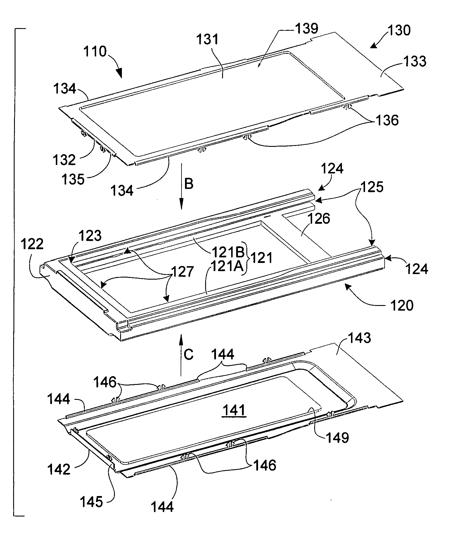
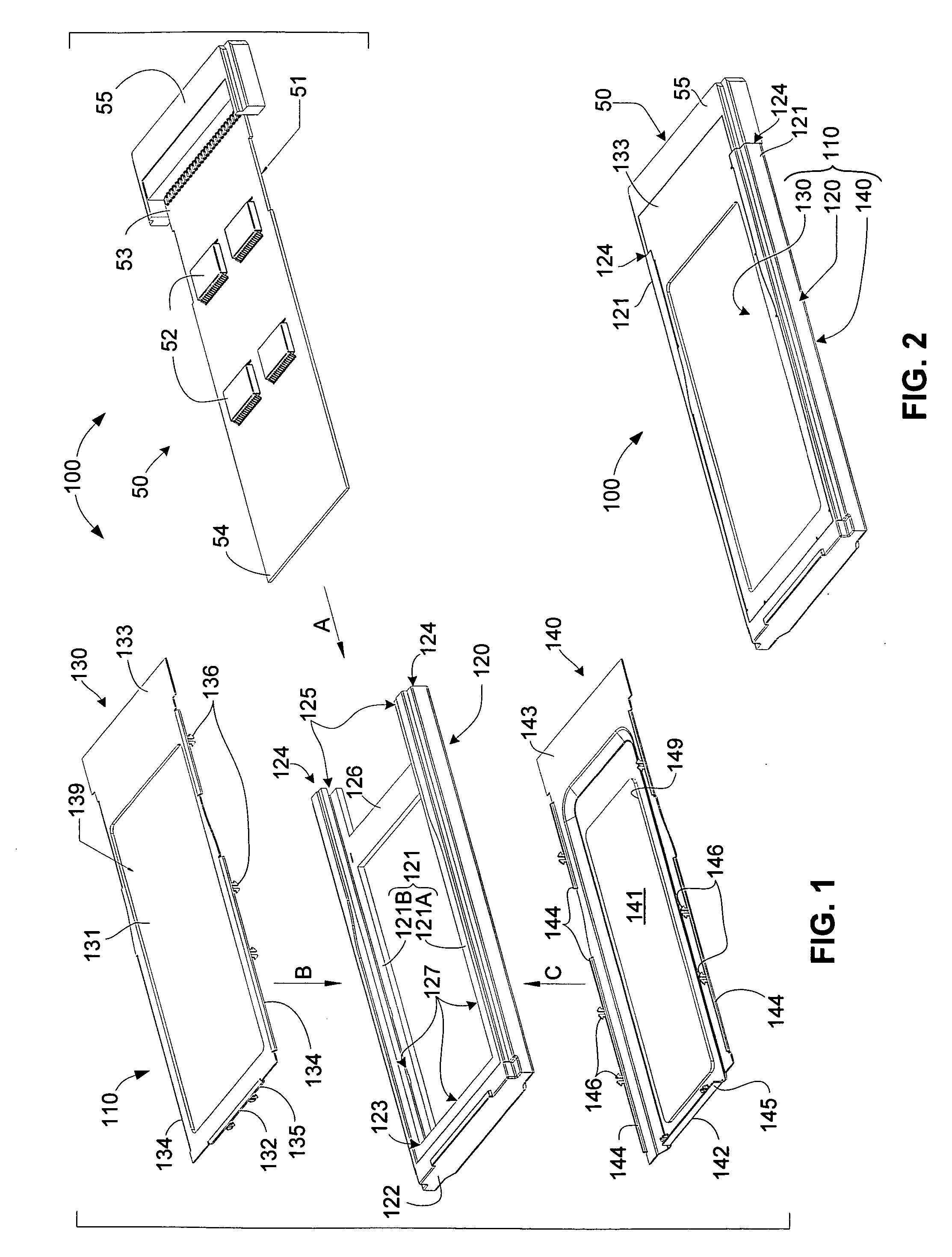
[0027]FIGS. 1 and 2 are exploded perspective and assembled perspective views, respectively, showing a PC card 100 formed by a PCB assembly 50 and a PC card frame kit 110 according to an embodiment of the present invention.

[0028] Referring to the right side of FIG. 1, PCB assembly 50 generally includes a PCB 51 and a connector 55. PCB 51 is sized and constructed according to a predefined form factor (e.g., consistent with the PCI Express Architecture developed by Intel Corp. of Santa Clara, Calif.), and includes one or more ICs 52 and / or other electronic components mounted thereon. Connector 55, which also conforms to the selected form factor, is mounted onto a back edge 53 of PCB 51, and includes pins (not shown) that communicate with ICs 52 via corresponding traces (also not shown) formed on PCB 51 according to well-known practices. PCB 51 also includes a leading (first) edge 54 that is inserted into frame 120 in the manner described below.

[00...


PUM


Abstract

A PC card frame kit for housing a printed circuit board (PCB) assembly including a PC board and a connector mounted on a back edge of the PCB. The frame kit includes a frame including first and second parallel side rails and an end rail extending between first ends of the first and second side rails. A pair of panels is connected to opposite sides of the frame by substantially identical (e.g., male-type) connection structures that are provided on both panels. A pair of ground contacts is provided on opposite sides of the PCB assembly connector that respectively contact the two panels. A metal support (shroud) is incorporated into the frame to receive the ends of the connection structures extending from both panels.

Description

FIELD OF THE INVENTION [0001] The present invention generally pertains to PC card-like devices, and more particularly to housing structures for PC cards, and to methods for assembling PC cards into such housing structures. BACKGROUND OF THE INVENTION [0002] Portable Computer Memory Card International Association (PCMCIA) Cards, which are now simply referred in industry as “PC cards”, are credit card-size peripheral devices that are used, for example, to add memory, mass storage, and I / O capabilities to computers. PC cards includes a small printed circuit board (PCB) encased in a rugged housing, and are produced according to a variety of form factors. Each PC card typically includes a pin / socket-type connector located at one end of the housing that facilitates convenient pluggable connection of the PC card to a host system, although other connector types (e.g., surface mount) are also used. The PC card connector and data interchange formats are standardized, and mechanical and electr...

Claims


Application Information

Patent Timeline
IPC IPC(8): H05K7/14
CPCH05K5/0269
Inventor CHIOU, REN-KANGLEE, EDWARD W.WANG, KUANG-YU
Owner SUPER TALENT ELECTRONICS
Why Eureka
Try Eureka