Prediction of dynamic ground effect forces for fixed wing aircraft

a technology of dynamic ground effect and fixed wing aircraft, which is applied in the direction of instruments, cad techniques, analogue processes for specific applications, etc., can solve the problems of increasing lift, reducing induced drag, and expensive experimental determination of these forces

Inactive Publication Date: 2005-09-08
HONEYWELL INT INC
View PDF7 Cites 26 Cited by
  • Summary
  • Abstract
  • Description
  • Claims
  • Application Information

AI Technical Summary

Benefits of technology

[0009] The angle of attack of the airfoil is then expressed as a function its downwash velocity, the geometry of the airfoil, and a series representation of its vorticity distribution. The geometry of the airfoil includes but is not limited to one or more of the wingspan, chord distribution, lift-slope, and twist distribution. The vorticity distribution is calculated from the angle of attack by substituting values for the angle of attack, a value for the height above the ground, a value of descent rate into the ground, and values for a geometry of the airfoil. Finally, aerodynamic forces and moments on the airfoil are calculated from the vorticity distribution. These aerodynamic forces include but are not limited to lift and drag. The aerodynamic moments include but are not limited to pitching moment.
[0010] In another embodiment a method for calculating dynamic ground effects of fixed wing aircraft in autoland systems, autopilot systems, or computer simulations is presented. An airfoil of the fixed wing aircraft and its trailing vortices are modeled as a lifting line with trailing vortex sheets at a certain height above the ground. The effects of interference from the ground on the trailing vortices is modeled as an image lifting line with trailing vortex sheets at a dis...

Problems solved by technology

These theoretical and experimental studies have shown that lift increases, induced drag decreases and the pitching moment becomes nose-down on fixed-wing aircraft experiencing ground effects.
The experimental...

Method used


Image

  • Prediction of dynamic ground effect forces for fixed wing aircraft
  • Prediction of dynamic ground effect forces for fixed wing aircraft
  • Prediction of dynamic ground effect forces for fixed wing aircraft

Examples


Embodiment Construction

[0024] A map of aerodynamic forces throughout the flight envelope is needed to permit the design of safe autoland and autopilot systems. It is also needed to simulate aircraft performance under different conditions and to improve designs. The dynamic ground effects aircraft experience as they ascend from and descend to the ground are an important part of the flight envelope. As a result, a prediction model for dynamic ground effects is needed that is simple enough to be incorporated into the design of safe autoland and autopilot systems and computer simulations used in the design of aircraft.

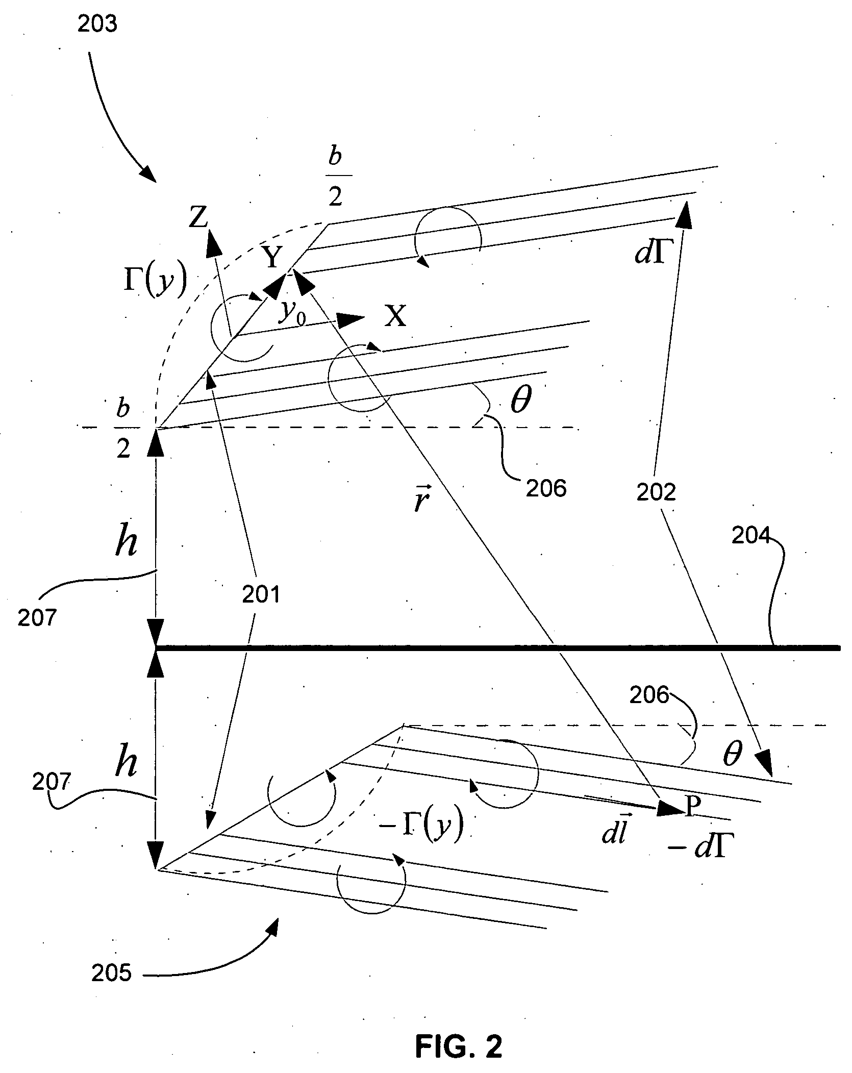
[0025] According to an embodiment of the present invention, a method of calculating dynamic ground effects on fixed wing aircraft which extends Prandtl's lifting line theory by using an image vortex system with lifting line and vortex sheet under the ground to satisfy zero normal velocity at the ground is presented.

Modified Lifting Line Theory

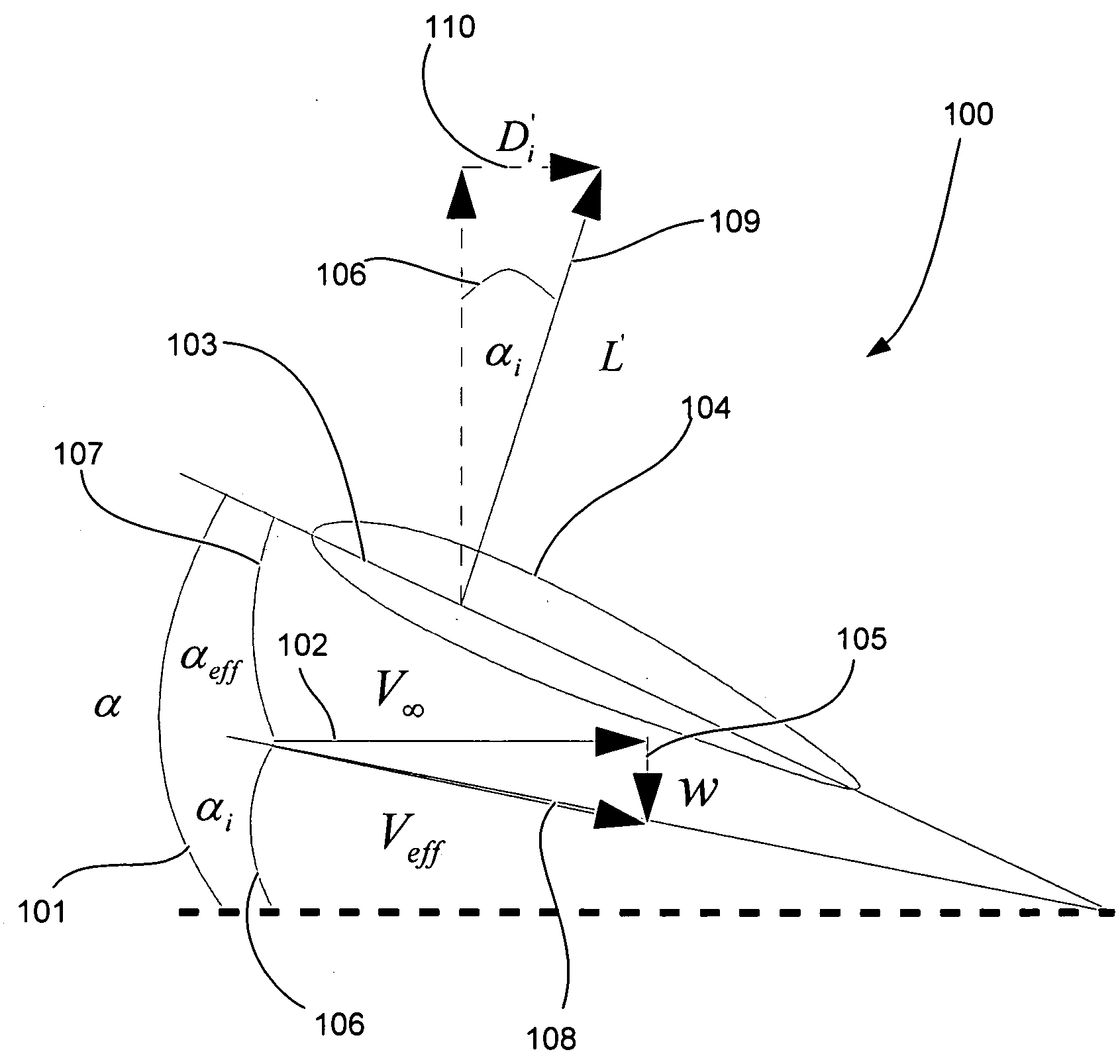
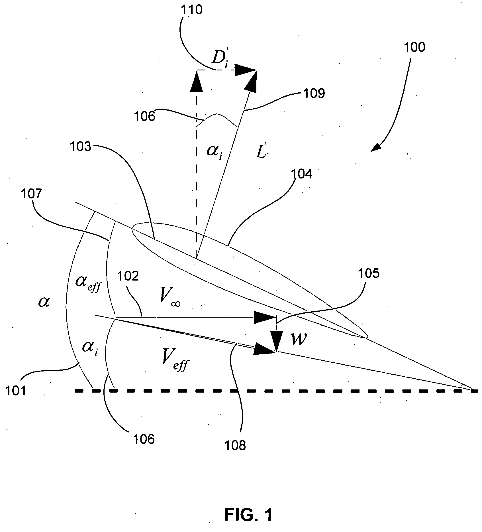
[0026]FIG. 1 is a schematic diagram depicting flo...


PUM


Abstract

Embodiments of the present invention relate to methods for calculating the aerodynamic forces and moments on fixed wing aircraft experiencing dynamic ground effects in subsonic flight. An airfoil and its trailing vortices are modeled as a lifting line with trailing vortex sheets and an image lifting line with trailing vortex sheets. The lifting line is located at a certain height above the ground and its image is located at an equal height below the ground, in order to satisfy a boundary condition of zero normal velocity at the ground. A downwash velocity at the airfoil is expressed as the sum of the downwash velocities from the lifting line and its image and is dependent on the height above the ground. The angle of attack of the airfoil is then expressed as a function its downwash velocity, the geometry of the airfoil, and a series representation of its vorticity distribution. The vorticity distribution is calculated from the angle of attack by numerical substitution. Aerodynamic forces and moments on the airfoil are calculated from the vorticity distribution. In another method, a lifting surface and image lifting surface are used to model an airfoil. These methods have particular use in autoland systems, autopilot systems and computer simulations.

Description

BACKGROUND OF THE INVENTION [0001] 1. Field of the Invention [0002] Embodiments of the present invention relate to methods for predicting dynamic ground effect forces on fixed wing aircraft. More particularly, embodiments of the present invention relate to methods for calculating the aerodynamic forces and moments on fixed wing aircraft experiencing dynamic ground effects in subsonic flight. These calculations are suitable for use in aircraft rigid body simulations and in aircraft control systems, such as autopilot and autoland systems. [0003] 2. Background Information [0004] Ground effects on aircraft have been observed and analyzed over several decades beginning almost from the inception of powered flight. Studies over this period have focused on the effects of aircraft maintaining a constant height near the ground. These theoretical and experimental studies have shown that lift increases, induced drag decreases and the pitching moment becomes nose-down on fixed-wing aircraft expe...

Claims


Application Information

Patent Timeline
IPC IPC(8): G06G7/48
CPCG06F2217/16G06F17/5009G06F2111/10G06F30/20
Inventor ARIYUR, KARTIK B.
Owner HONEYWELL INT INC
Why Eureka
Try Eureka