Method and apparatus for providing a DSG to an OOB transcoder

a transcoder and transcoding technology, applied in the field of cable television systems, can solve the problems of undesirable loss of rf bandwidth, large amount of valuable rf bandwidth, and the inability of the legacy set-top device to receive oob messages from the cable television network, and achieve the effect of freeing up bandwidth

Inactive Publication Date: 2005-09-08
GENERAL INSTR CORP
View PDF5 Cites 50 Cited by
  • Summary
  • Abstract
  • Description
  • Claims
  • Application Information

AI Technical Summary

Benefits of technology

[0011] By incorporating the one-way DSG to OOB transcoder of the present invention, a cable television system converting to DOCSIS DSG, or utilizing DOCSIS DSG, does not require an OM. For a pure DOCSIS two-way system with the two-way DSG to OOB transcoder, an RPD and

Problems solved by technology

Without these components in the headend of the cable television system, a legacy set-top device will not be able to receive OOB messaging from the cable television network, which is mandatory to properly receive a cable television signal in the DOCSIS DSG environment.
In operation, however, the OMs utilize a large amount of valuable RF bandwidth.
While the loss of this RF bandwi

Method used


Image

  • Method and apparatus for providing a DSG to an OOB transcoder
  • Method and apparatus for providing a DSG to an OOB transcoder
  • Method and apparatus for providing a DSG to an OOB transcoder

Examples


first embodiment

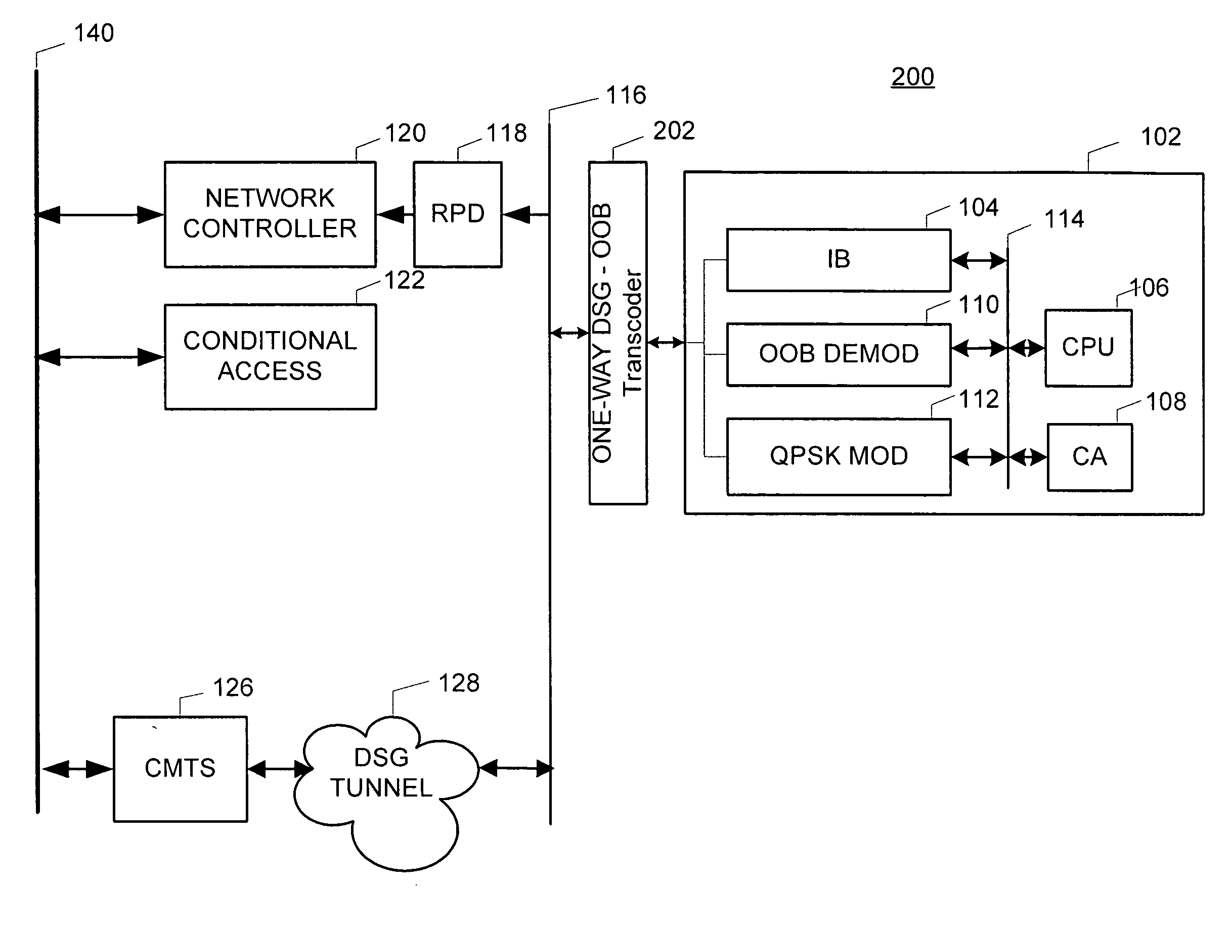
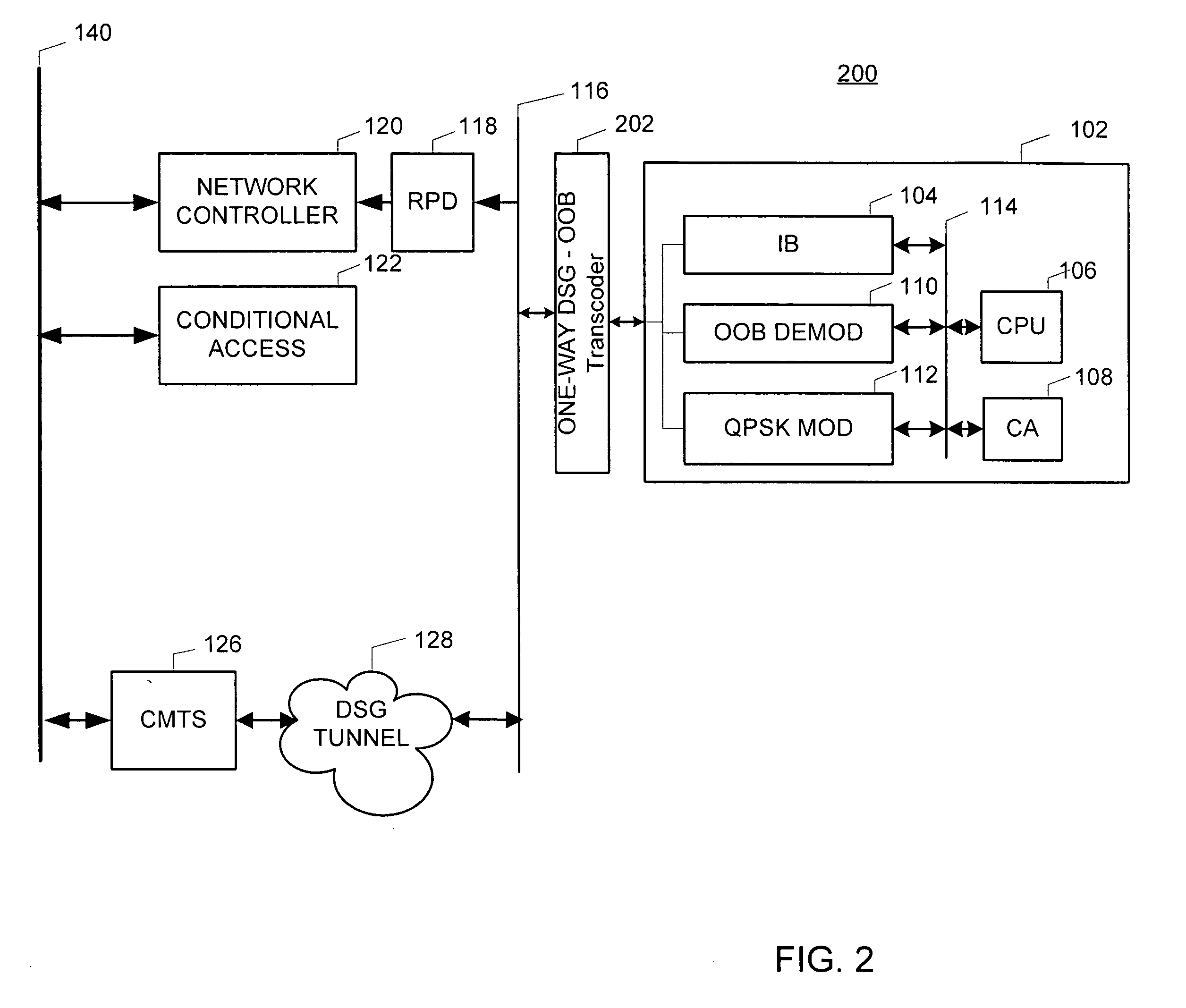
[0031]FIG. 2 is a simplified block diagram of an exemplary system in accordance with the present invention utilizing a one-way DSG to OOB transcoder 202. Comparing system 200 to prior art system 100, OM 124 is no longer required in this system 200 as compared to system 100 as a result of the one-way DSG to OOB transcoder 202. Thus, the bandwidth consumed by that OM 124 is now available for other purposes. The details of the DSG to OOB transcoder 202 are discussed in greater detail in FIG. 3.

[0032]FIG. 3 is a detailed block diagram of the one-way DSG to OOB transcoder 202 depicted in FIG. 2. One-way DSG to OOB transcoder 202 comprises components that bridge the DSG tunnel 128 to the legacy set-top device 102. One-way DSG to OOB transcoder 202 only transcodes the downstream DSG tunnel 128, and thus, does not transcode the return path to the legacy set-top device 102.

[0033] One-way DSG to OOB transcoder 202 comprises a filter 304 that separates the DSG tunnel 128 from the remainder of...

second embodiment

[0036] In this second embodiment, network controller 120, RPD 118 and OM 124 are not present in system 400. All OOB communications to legacy set-top device 102 are replaced by the DSG tunnel 128 and the DOCSIS return path, which are proxied by the two-way DCG to OOB transcoder 402. The details of the two-way DSG to OOB transcoder 402 are discussed in further detail in FIG. 5.

[0037]FIG. 5 is a detailed block diagram of the two-way DSG to OOB transcoder 402 as provided by the second embodiment of the present invention. To enable two-way DOCSIS communication to the legacy set-top device 102, two-way DSG to OOB transcoder 402 comprises tuner / QPSK demodulator 522, which tunes to the frequency carrying the proprietary OOB return channel. The two-way DSG to OOB transcoder 402 also demodulates any return communication from the legacy set-top device 102 intended for the DSG tunnel 128, which ultimately reaches the conditional access system 122. The practice of locating and tuning to the prop...


PUM


Abstract

The present invention is a method and apparatus for providing a DSG to OOB transcoder in a cable television system comprising a legacy set-top device 102. In the first embodiment, a one-way DSG to OOB transcoder 202 acts as a proxy device for OOB messages to the DSG tunnel 128. Once an OOB message is generated, the OOB message is transmitted to the DSG tunnel 128. The DSG to OOB transcoder 202 of the present invention then captures the OOB message, and communicates the OOB message to the legacy set-top device 102. In a second embodiment of the invention, the legacy set-top device 102 may communicate return communications to the DSG to OOB transcoder 402 by generating a QPSK message. The QPSK message is then translated to an OOB message comprising DOCSIS content.

Description

FIELD OF THE INVENTION [0001] The present invention relates to the field of cable television systems, and more particularly, to a method and apparatus for providing OOB messaging functionality to set-top devices without DOCSIS capability in a DOCSIS DSG cable television system. BACKGROUND OF THE INVENTION [0002] Currently, cable operators are beginning to convert their cable television systems to a technology specification known as the Data Over Cable Interface Specification (DOCSIS). Among its many advantages, DOCSIS brings seamless interoperability to cable technology. Thus, cable architecture components such as cable modems and set top devices can be “mixed and matched” freely, without regard to the particular manufacturer of each component of the cable television system. [0003] Recently, several players in the cable television industry joined together to develop a specification for defining the DOCSIS interface requirements between the cable operator and the equipment at each ca...

Claims


Application Information

Patent Timeline
IPC IPC(8): H04L5/14H04N7/16H04N7/173
CPCH04L12/2801H04N21/235H04N21/6118H04N21/435H04N21/42676
Inventor STONE, CHRISTOPHER J.GRZECZKOWSKI, RICHARD S.
Owner GENERAL INSTR CORP
Why Eureka
Try Eureka