
Volume-flexible body fillable with a fluid element

a fluid element and body technology, applied in the field of volume-flexible body fillables, can solve the problems of increasing the difficulty of inflating and deflating the body, the fluid line must move along with the height adjustment, and the usable surface is reduced, so as to improve the mechanical stability of the body consisting of stacked and folded sections, the effect of improving the unrestricted inflation and deflation of the body

Inactive Publication Date: 2005-09-15
HOERBIGER AUTOMOTIVE KOMFORTSYST
View PDF2 Cites 0 Cited by
  • Summary
  • Abstract
  • Description
  • Claims
  • Application Information

AI Technical Summary

Benefits of technology

[0011] According to an advantageous embodiment of the invention, the segment of the connection piece lying inside the body forms a hinge axis whereby the sheets stacked on top of one another are folded along this hinge axis. On the other hand, mechanical reinforcement of the hinge area is thereby provided and, on the other hand, the best unrestricted inflation and deflation of the folded, stacked sections of the body is ensured.
[0013] According to the invention, the connection piece transforms at the inner side of the sheets into an air diffuser with radial openings essentially branching out in a radial manner inside the body to further improve unrestricted inflation and deflation of the body. On the one hand, the sheets are kept at a distance apart by the air diffuser in the region thereof so that its radial openings are kept free. On the other hand, the fluid supply or discharge is distributed across a large area to make possible a rapid and quiet inflation and deflation.
[0014] These advantages can be enhanced if the connection piece is transformed on the inner side of the edge into two essentially radial air diffusers branching off in opposite directions within the interior of the body.
[0015] According to an additional characteristic of the invention, the mechanical stability of bodies consisting of stacked and folded sections can be increased also in this case if the air diffuser forms a hinge axis and the stacked sheets are folded along this hinge axis.
[0016] Fluid exchange between the individual sections can be prevented even in an embodiment of this type if the cavity of the body is divided by the air diffuser into two separate sections, possibly along the entire hinge axis, whereby the separate sections are in communication only by the radial openings in the connection piece.
[0017] An advantageous embodiment including all of the above-described variations of design has the characteristics that narrow radial elements project from the segment of the connection piece or the air diffuser lying inside the body whereby the radial elements preferably extend between said radial opening and extend between the sheets lying on top on one another. The sheets are kept at a distance apart by these radial elements across wide areas and away from the connection piece or the air diffuser, which ensures free inflowing or outflowing of fluid through the connection piece or the air diffuser from a large area of the body.

Problems solved by technology

Such connection pieces are therefore either on the side facing the user ,and thus decreasing the usable surface since they should not be felt by the user, or the connection pieces are on the side facing the carrier whereby they require recesses or special re-routing of the fluid line whereby they are additionally difficult to access.
Connection pieces arranged on the usable surface have the additional disadvantage that the connected fluid line must move along with the height adjustments, especially in case of bodies with a capability of large adjustment in height.
In addition, this arrangement makes inflating and deflating of the body more difficult, especially if the body is very flat or possibly if the outer contour is shaped very irregular and the opening of the connection piece is covered by the opposed sheet of material.

Method used


Image

  • Volume-flexible body fillable with a fluid element
  • Volume-flexible body fillable with a fluid element
  • Volume-flexible body fillable with a fluid element

Examples


Embodiment Construction

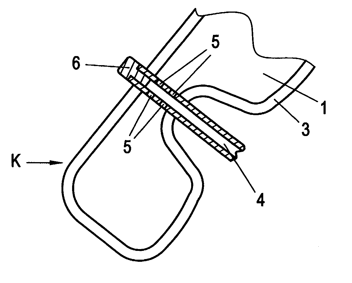
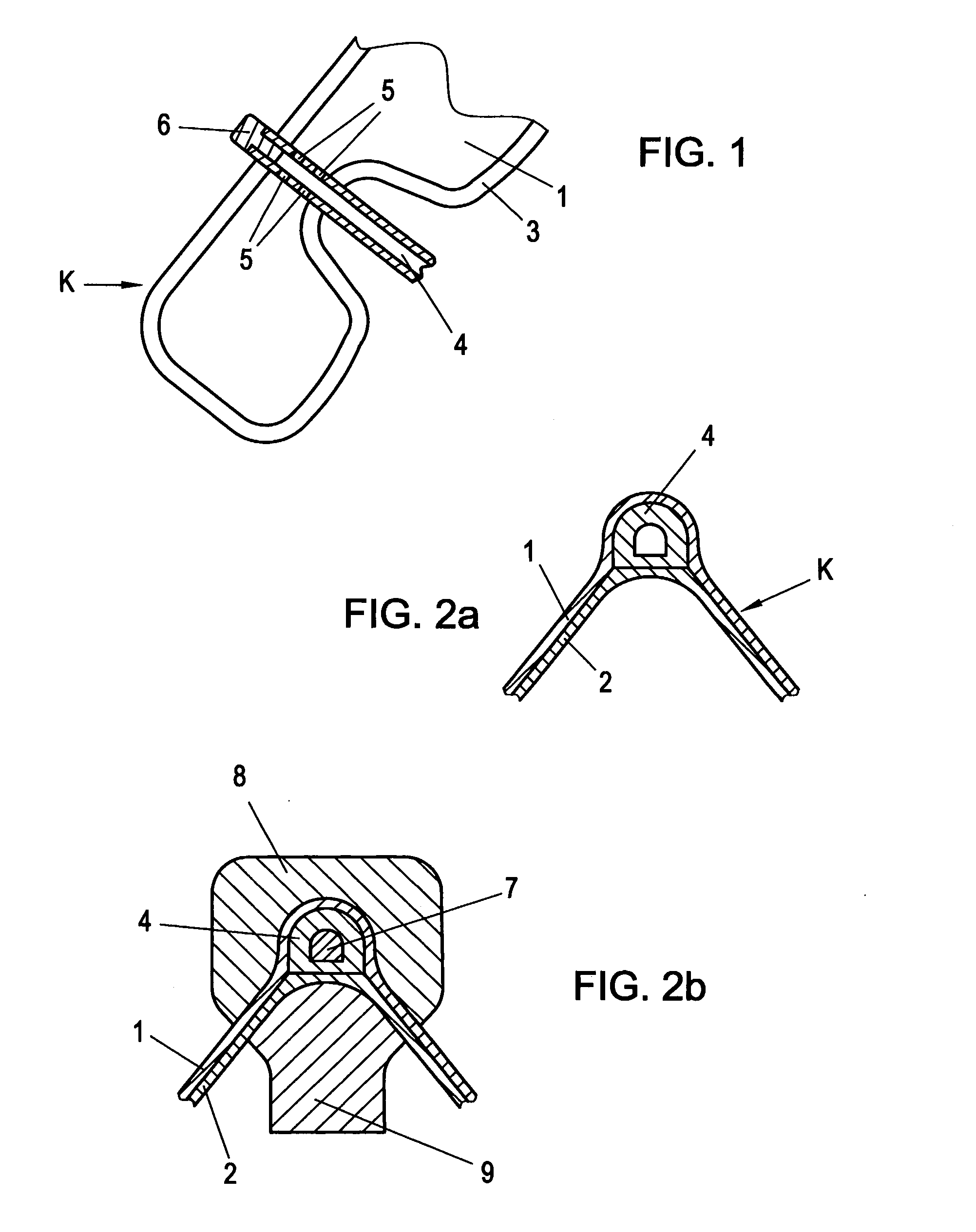
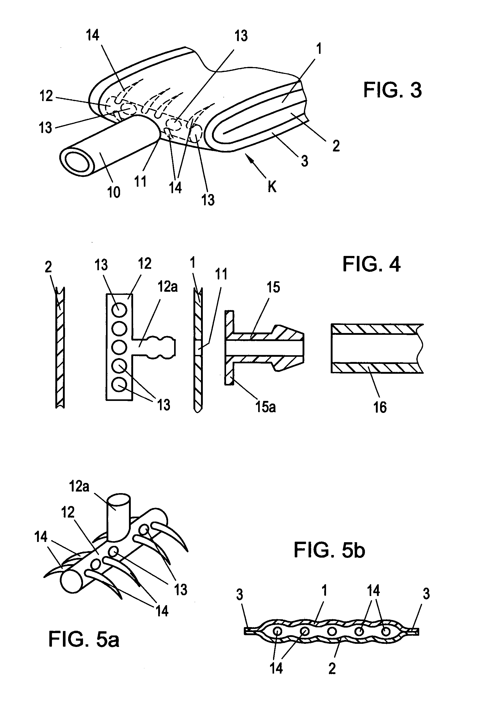
[0026] A body K fillable with a fluid and being therefore flexible in its volume consists of two sheets 1,2 facing each other whereby the sheets are sealed together along their outer contour by a welded bond 3 (only the top sheet 1 is visible in FIG. 1). The sheets 1, 2 can also be attached to one another through other bonding methods, i.e., through adhesion. The actual welded bond 3 is broken at two opposed points and a connection piece 4 is inserted between the two sheets 1, 2 parallel to the plane of the flat surface of the body K or parallel to the plane of the outer contour of the body to facilitate the supply and discharge of fluid whereby the connection piece 4 protrudes again from the body K on the opposite side of the point of entry.

[0027] The connection piece 4 is provided with radial openings 5 through which the fluid can flow into the body K and flow out from there across a greater length of the connecting piece 4. Lower flow velocity is made possible thereby for the fl...


PUM


Abstract

A volume-flexible body fillable with a fluid including two sheets preferably welded together along the peripheral edges and preferably made of synthetic material, as well as a connection piece for a line for fluid inlet or outlet, preferably gas, especially air, into or from the body, whereby the connection piece (4, 10, 12a) extends into the body (K) from the location of entry parallel to the plane defined by the peripheral edge (3) and possibly extending past the location of entry parallel to the plane defined by the peripheral edge (3) and leading through the edge and / or penetrating one of the sheets (1) and leading into the interior of the body (K). The connection piece (4) is provided with radial openings (5) whereby the connection piece (4) extends completely through the body (K) and leads again to the outside through the edge (3) at a point opposite the place of entry to improve inflation and deflation capability and to maximize additionally the usable surface and / or to accomplish installation in the best possible way.

Description

BACKGROUND OF THE INVENTION [0001] 1. Field of the Invention [0002] The invention relates to a volume-flexible body fillable with a fluid including two sheets, preferably welded together along the peripheral edges and preferably made of synthetic material, as well as a connection piece for a line for fluid inlet or outlet, preferably gas, especially air, into or from the body, whereby the connection piece extends into the body from the location of entry parallel to the plane defined by the peripheral edge and possibly extending past the location of entry parallel to the plane defined by the peripheral edge and leading through the edge and / or penetrating one of the sheets and leading into the interior of the body. [0003] 2. The Prior Art [0004] In case of contour-adjustable seats, especially vehicle seats or aircraft seats, there are often provided inflatable bodies fillable with air or another gas in the form of a cushion making conformity of the shape of the seat possible. Tireless...

Claims


Application Information

Patent Timeline
IPC IPC(8): A47C7/26A47C27/08B60N2/90
CPCA47C4/54B60N2/4415A47C27/081B60N2/914
Inventor BICHLER, THOMAS
Owner HOERBIGER AUTOMOTIVE KOMFORTSYST
Learn More