Fastening clip for jewelry, handbags, etc.
- Summary
- Abstract
- Description
- Claims
- Application Information
AI Technical Summary
Benefits of technology
Problems solved by technology
Method used
Image

Examples
Example
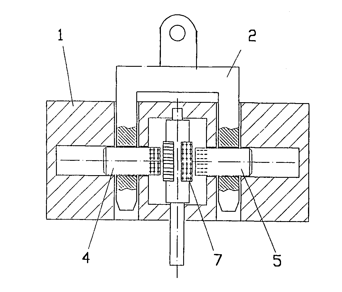
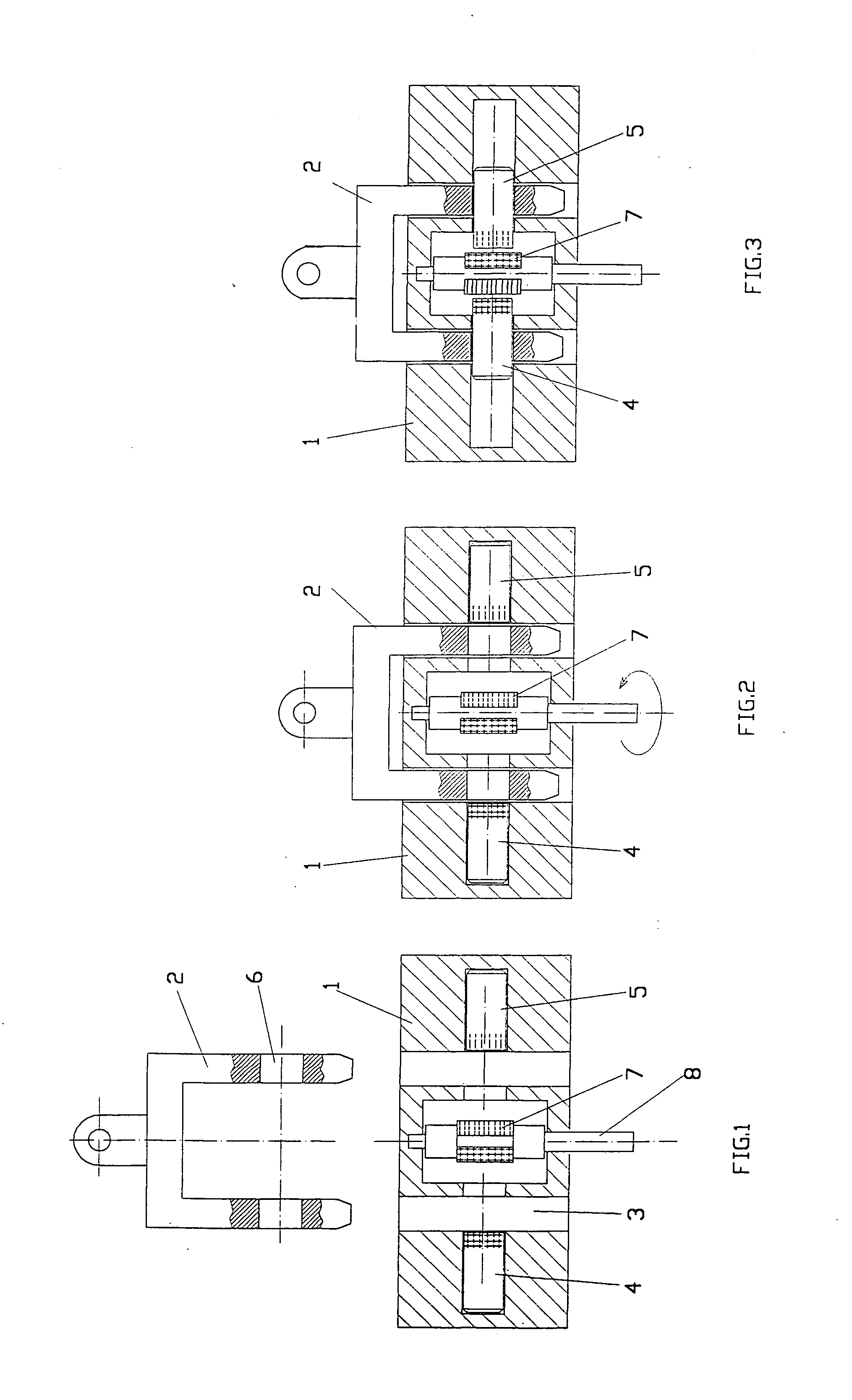
[0012] As can be seen in FIGS. 1 to 3, in a first embodiment of the invention, fastening of the clip is obtained through magnetic pins 4 and 5, arranged opposing each other and contained in the body 1. Pins 4 and 5 are inserted into the corresponding holes 6, formed on the anchor 2. The axial sliding of the two magnetic pins 4 and 5 is caused by a magnet 7 arranged between the aforementioned pins and mounted on a support 8, rotatable about its axis.
[0013] As can easily be seen from FIGS. 1 to 3, the axial movement of the two pins 4 and 5 is a consequence of the fact that the magnetic poles of the aforementioned pins are of the same sign or of opposite sign with respect to the corresponding magnetic poles of the central magnet 7.
[0014] In operation, with the fastener open (see FIG. 1), the magnetic poles of pins 4 and 5 are of the same sign as the opposing magnetic poles of the central magnet 7 for which reason, due to the repulsive force, they remain inside their seats in body 1. ...
Example
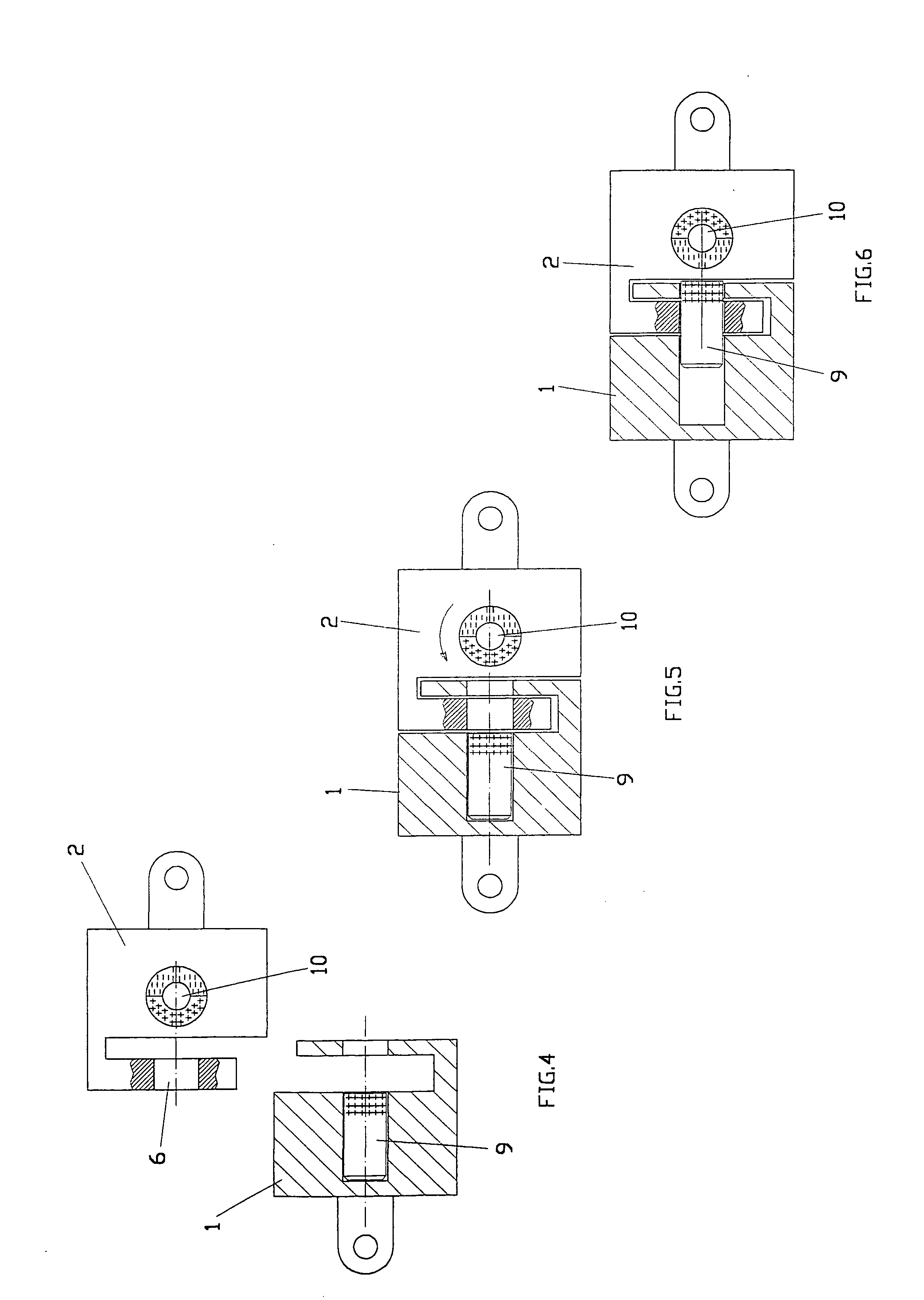
[0015] As can be seen in FIGS. 4 to 6, in a second embodiment of the invention the fastening between the body 1 and the anchor 2 is carried out with the use of a magnetic pin 9 and a magnet 10. Pin 9 is inserted in body 1 and is adapted to slide axially whereas magnet 10 is inserted in anchor 2 and is adapted to rotate 180°. As can easily be seen from FIGS. 4 to 6, the axial sliding of pin 9 is a consequence of the fact that the magnetic poles of the pin 9 and of the magnet 10 are of the same sign or of opposite signs.
[0016] In operation, in the open state of the fastener (see FIG. 5), the opposing poles of the pin 9 and of the magnet 10 are of the same sign for which reason, due to the repulsive force, the slidable pin 9 remains inside its seat in the body 1. With the rotation by 180° of magnet 10, the polarities of the pin 9 and the magnet 10 are thus inverted, for which reason a magnetic attraction force is applied to pin 9, which, sliding, inserts into the hole 6, carrying out ...
Example
[0017] As can be seen in FIGS. 7 to 9, in a third embodiment of the invention, the fastening between the body 1 and the anchor 2 is carried out with the use of two magnetic pins 11 and 12, arranged opposite one another and both inserted in the aforementioned body 1, wherein one is fixed and the other is adapted to slide axially. The fastening operation takes place with the manual insertion of the anchor 2 in the recess 3 (FIG. 7), which is locked by the mobile pin 12 which, having the magnetic pole with the opposite sign to the magnetic pole of the fixed pin 10, is attracted and thus inserted into the hole 6 (FIG. 8), carrying out the desired fastening. As can be seen in FIG. 9, the unfastening operation is carried out by inserting a magnet 14, orientated so as to have a magnetic pole of opposite sign to the magnetic pole of the mobile pin 12, into the intermediate recess 13, which brings about a repulsive force that takes the aforementioned pin back into its seat and thus frees the...
PUM
 Abstract
Description
Claims
Application Information
 - R&D Engineer
- R&D Manager
- IP Professional
- Industry Leading Data Capabilities
- Powerful AI technology
- Patent DNA Extraction
Browse by: Latest US Patents, China's latest patents, Technical Efficacy Thesaurus, Application Domain, Technology Topic.
© 2024 PatSnap. All rights reserved.Legal|Privacy policy|Modern Slavery Act Transparency Statement|Sitemap