
Thin-type display device

a display device and thin-type technology, applied in the direction of identification means, electrical apparatus casings/cabinets/drawers, instruments, etc., can solve the problems of increased time and labor, increased cost, and increased cost,

Inactive Publication Date: 2005-09-22
SHARP KK
View PDF10 Cites 32 Cited by
  • Summary
  • Abstract
  • Description
  • Claims
  • Application Information

AI Technical Summary

Benefits of technology

[0022] The present invention is characterized in that a concave or convex for preventing said projection from escaping from said rail is provided on the inner periphery of said rail or the outer periphery of said projection.

Problems solved by technology

However, the changing operation between the landscape and portrait orientation is not completed at one step in the screen orientation changing mechanism of the above-mentioned prior art flat panel display apparatus since it is conducted at two steps of rotary movements by the rotary axes A and B. Specifically if the changing mechanism is applied to large screen display apparatus, an extended period of time and labor is expended.
Since the rotation center is not in the vicinity of the center of the screen, the rotary movement of the display unit at this time is larger than that around the central portion of the display unit, so that ease of rotation may be lost.
As a result, a process for changing the orientation of the display screen may become very unstable.

Method used


Image

  • Thin-type display device
  • Thin-type display device
  • Thin-type display device

Examples


first embodiment

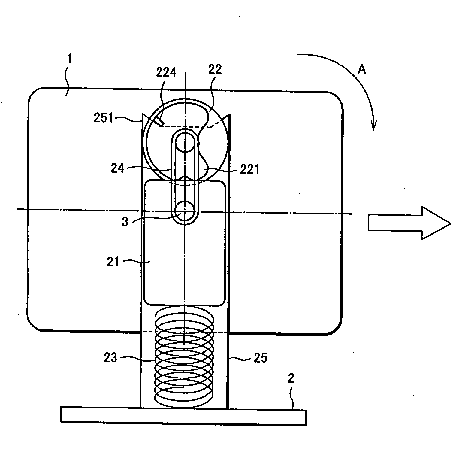
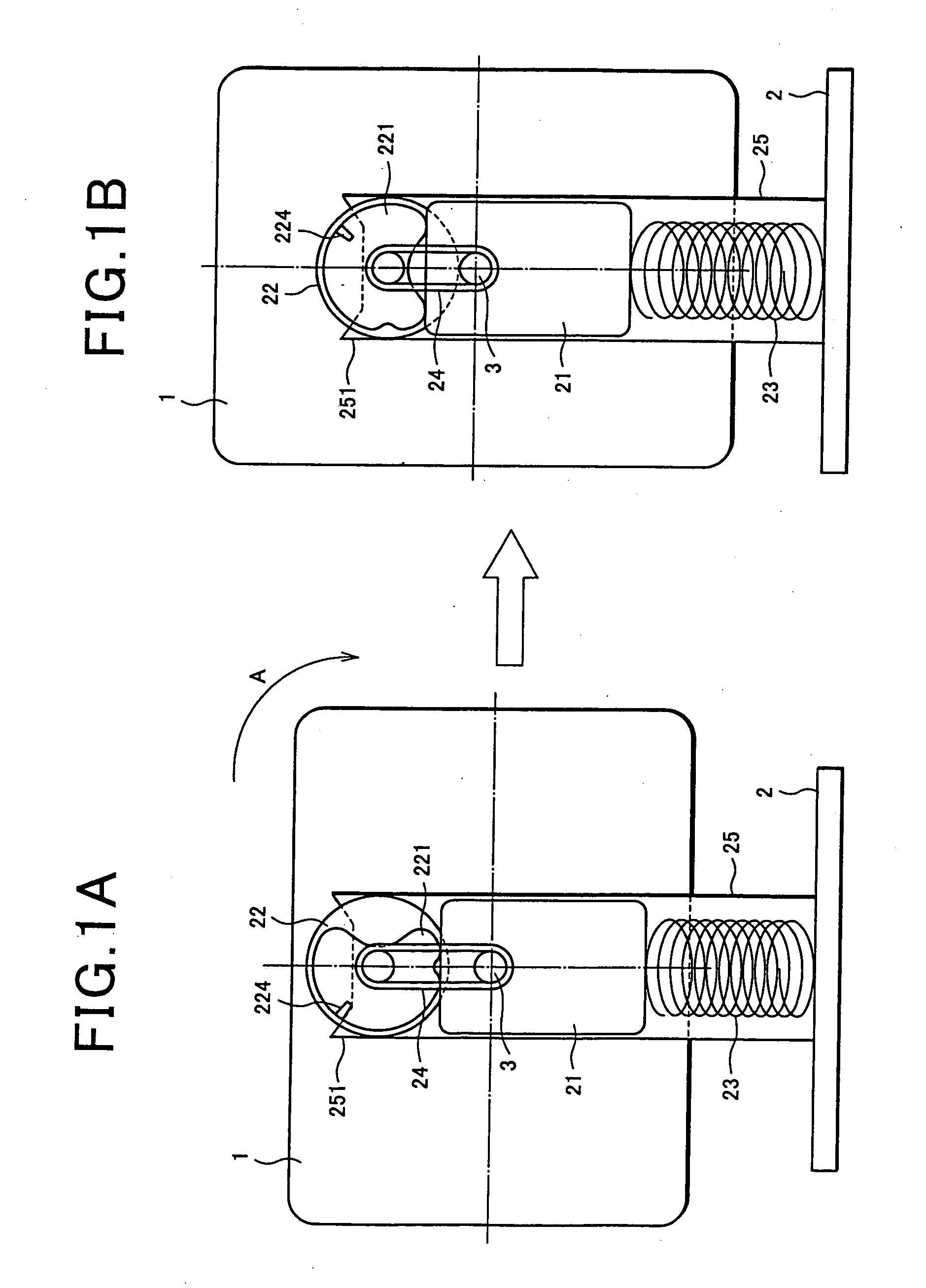
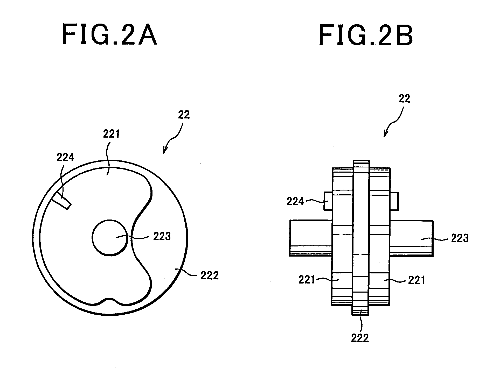
[0038] Now, a first embodiment of the flat panel display apparatus of the present invention will be described in detail with reference to FIGS. 1A through 3B. FIGS. 1A and 1B show a first embodiment of a flat display apparatus of the present invention. FIGS. 1A and 1B are rear sectional views showing the landscape (horizontal) and portrait (vertical) orientation, respectively. FIGS. 2A and 2B are views showing a cam portion in the flat panel display apparatus of the present embodiment. FIGS. 2A and 2B are front and elevational views, respectively. FIGS. 3A and 3B are views showing the flat panel display apparatus of the present embodiment. FIGS. 3A and 3B are elevational sectional views of a main part showing the landscape and portrait screen orientation, respectively.

[0039] As shown in FIGS. 1A and 1B, the flat panel display apparatus of the present embodiment comprises a flat panel display unit 1 having a substantially rectangular display screen, a stand unit 2 which supports the...

second embodiment

[0052] Now, a second embodiment of the flat panel display apparatus of the present invention will be described in detail with reference to FIGS. 4A through 6B. Like components are designated by like reference numerals in FIG. 1. The description of them will be omitted. FIGS. 4A and 4B show the second embodiment of the flat panel display apparatus of the present invention. FIGS. 4A and 4B are rear sectional views showing the landscape and portrait orientation, respectively. FIGS. 5A and 5B are front and elevational views, respectively, showing the cam portion in the flat panel display apparatus of the present embodiment. FIGS. 6A and 6B show a main part of the flat panel display apparatus of the present embodiment. FIGS. 6A and 6B are elevational sectional views of a main part showing the landscape and portrait orientation, respectively.

[0053] The flat panel display apparatus of the present embodiment comprises a biasing means 23, vertical lifting axis 21 and cam portion 22, which a...

third embodiment

[0059] Now, a third embodiment of a flat panel display apparatus of the present invention will be described in detail with reference to FIGS. 7A through 9B. Components which are identical to those in the first embodiment are represented by identical reference numerals. Description thereof will be omitted. FIGS. 7A and 7B show the third embodiment of the flat panel display apparatus of the present invention and are rear sectional views showing the portrait and landscape orientation of the display unit, respectively. FIGS. 8A and 8B are front and elevational views, respectively, showing a cam portion in the flat panel display apparatus of the present embodiment. FIGS. 9A and 9B show a main part of the flat panel display apparatus of the present embodiment and are elevational sectional views showing the portrait and landscape orientation of the display unit, respectively.

[0060] The flat panel display apparatus of the present embodiment of FIGS. 7A and 7B is substantially identical wit...


PUM


Abstract

A flat panel display apparatus is provided which is capable of conducting a transition of a display unit between the landscape and portrait orientation at one step and rotating around the substantial central portion of said display unit. The flat panel display apparatus includes a thin flat display unit (1) having a rectangular shape display screen thereon; a stand unit (2) for supporting said display unit (1); and a horizontal rotary axis (3) which is secured to the display unit (1) on its rear side in the substantial center thereof and which holds said display unit (1) so that display unit (1) is rotatable by at least 90 relative to said stand unit (2) and is characterized in that said display apparatus is provided with translational motion means (21, 22, 23) which causes the translational motion of said display unit (1) in a vertical direction in an interlocking manner with the rotation of said horizontal rotary axis (3).

Description

FIELD OF THE INVENTION [0001] The present invention relates to a flat panel display apparatus such as liquid crystal display apparatus and in particular to a flat panel display apparatus having a display screen which is tiltable into landscape (horizontal) orientation or portrait (vertical) orientation. BACKGROUND OF THE INVENTION [0002] Various mechanisms which change the display screen of the flat panel display apparatus such as liquid crystal display apparatus to be tilted into a landscape (horizontal) orientation or portrait (vertical) orientation have heretofore been proposed. A screen orientation changing mechanism of a simple structure which conducts a combination of an operation for turning a display unit with an operation for moving the display unit in a vertical direction without using separate turning mechanism and vertical moving mechanism is disclosed in, for example, JP-A-Hei 11-338363. [0003] In this mechanism, a bar like connecting member which is referred to as “lin...

Claims


Application Information

Patent Timeline
IPC IPC(8): F16M11/06G09F9/00
CPCF16M11/06F16M11/105Y10S248/92G09F9/00F16M11/24
Inventor SHIMIZU, MASAKIYOSHII, TAKASHI
Owner SHARP KK
Learn More