Medical imaging diagnosis apparatus

a diagnostic apparatus and imaging technology, applied in the field of medical imaging diagnosis apparatus, can solve the problems of not being able to determine the location of the problem, nothing is conceived to improve the blockage or oppression of the subject's blockage or oppression, so as to achieve the effect of reducing the blockage or oppression

Inactive Publication Date: 2005-09-22
SHIMADZU CORP
View PDF6 Cites 19 Cited by
  • Summary
  • Abstract
  • Description
  • Claims
  • Application Information

AI Technical Summary

Benefits of technology

[0011] It is an object of the invention to provide a medical imaging diagnosis apparatus capable of taking both of a PET image and an X-ray CT

Problems solved by technology

However, since the PET image only represent a state of accumulating and distributing the nuclide, it is not necessarily clear at what location of the human tissue the nuclide is present.
Therefore, blocked feeling or oppressed feeling of the subject person poses a problem.
However, according to the system, data provided by the X-ray CT apparatus is intended to

Method used


Image

  • Medical imaging diagnosis apparatus
  • Medical imaging diagnosis apparatus
  • Medical imaging diagnosis apparatus

Examples


Embodiment Construction

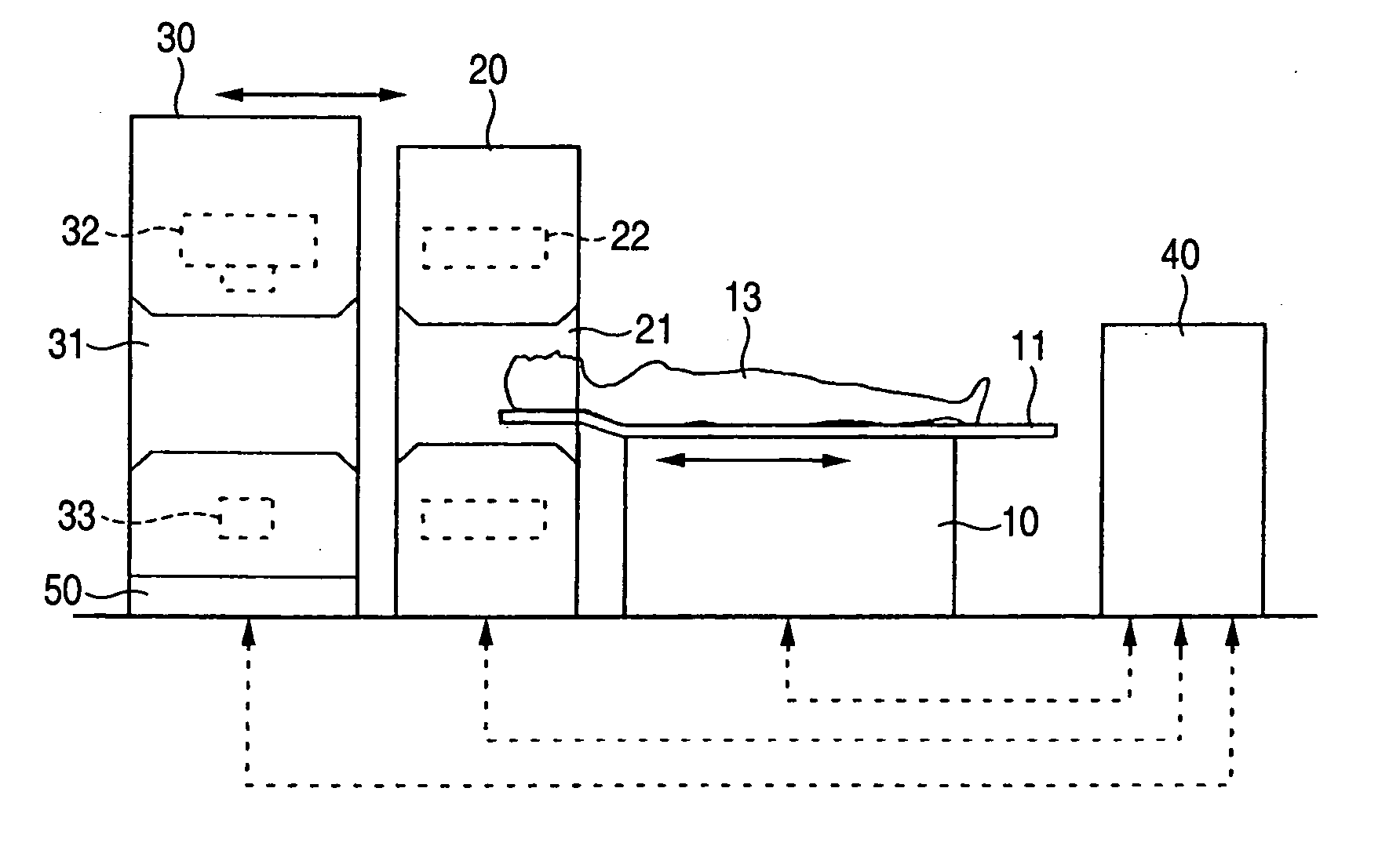
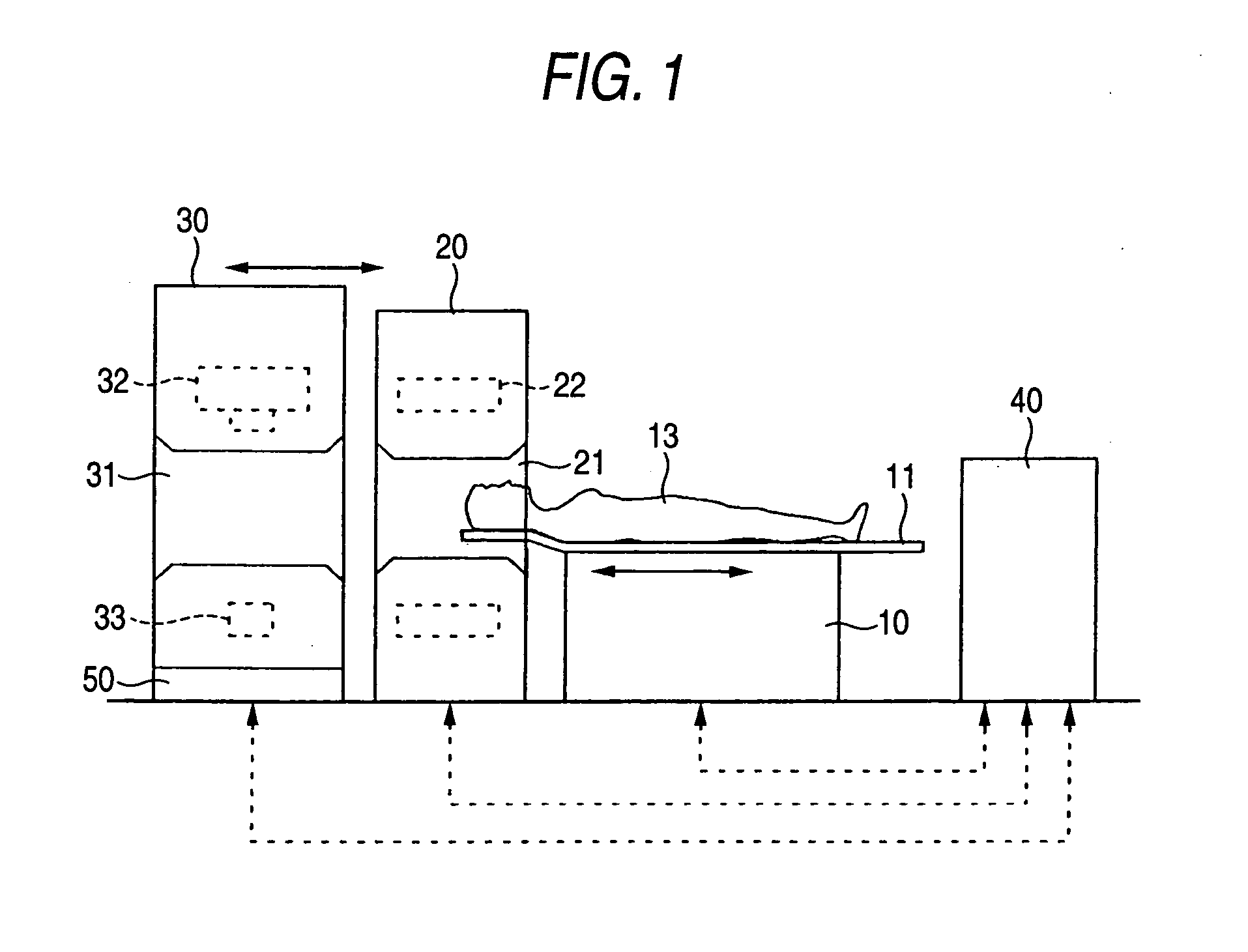
[0021] Next, a medical imaging diagnosis apparatus embodying the invention will be explained in reference to the drawings.

[0022] As shown by FIG. 1, a medical imaging diagnosis apparatus according to the invention includes an examination couch 10, a PET gantry 20, a CT gantry 30, and a console 40. The PET gantry 20 is a gantry for collecting PET data and is formed with a tunnel portion 21 at a center portion thereof and radiation detectors 22 for collecting the PET data. The radiation detectors 22 are arranged in a ring-like shape to surround the tunnel portion 21.

[0023] The tunnel portion 21 of the PET gantry 20 is for inserting a subject person 13 administered with a radioactive drug thereinto. A radiation emitted from the radioactive drug in the body of the subject person 13 is detected by the radiation detectors 22 arranged in the ring-like shape at a surrounding of the tunnel portion 21. Two of the radiation detectors 12 arranged in the ring-like shape detect simultaneous inc...


PUM


Abstract

A PET gantry and a CT gantry are placed in parallel such that the CT gantry becomes remoter to a common examination couch having a movable couch table top board mounted with a subject person and the CT gantry is made to be movable. The gantries are controlled by a control portion in a console. At first, the CT gantry is moved in a left direction to separate from the PET gantry so that whole body CT scan is carried out for the subject person in a direction from the leg portion to the head portion. Successively, the subject person is passed through a tunnel portion from the leg portion to the head portion by moving the couch table top board in a right direction in a state of considerably separating the CT gantry from the PET gantry to thereby carry out whole body PET scan.

Description

[0001] This application claims foreign priority based on Japanese patent application JP 2004-077578, filed on Mar. 18, 2004, the contents of which is incorporated herein by reference in its entirety. BACKGROUND OF THE INVENTION [0002] 1. Field of the Invention [0003] The present invention relates to a medical imaging diagnosis apparatus preferable for early detection of the cancer or the like, particularly relates to a medical imaging diagnosis apparatus capable of taking both of a PET (positron emission tomography) image and an X-ray CT image. [0004] 2. Description of the Related Art [0005] PET examination obtains a distributed image (tomographic image) of a positron emitting nuclide at a specific section of a subject person by calculation. After labeling a drug having a property of gathering to the focus of the cancer by a positron emitting nuclide, the drug is administered into the human body. In positron annihilation, gamma rays are emitted in directions opposed to each other by...

Claims


Application Information

Patent Timeline
IPC IPC(8): G01T1/161A61B6/00A61B6/03G01N23/00G01T1/24G01T7/00G21K1/12H05G1/60
CPCA61B6/032G01T1/1611A61B6/4417A61B6/037
Inventor INOUE, YOSHIHIROSUGIMURA, KOHSHIRO
Owner SHIMADZU CORP
Why Eureka
Try Eureka