Impeller vane configuration for a centrifugal pump

a centrifugal pump and impeller technology, applied in the field of centrifugal pumps, can solve the problems of less efficient radial outward flow direction of the vanes and less effective cutting edge in providing a cutting action on the solids, and achieve the effect of improving the hydraulics of the pump, efficient directing the influent, and aggressive profil

Inactive Publication Date: 2005-09-22
ENVIROTECH PUMPSYSTEMS INC
View PDF13 Cites 10 Cited by
  • Summary
  • Abstract
  • Description
  • Claims
  • Application Information

AI Technical Summary

Benefits of technology

[0011] In accordance with the present invention, an impeller vane configuration for use in centrifugal pumps, especially chopper pumps, is provided with a cutting edge that is particularly structured to retain an aggressive profile as the impeller wears down with use, and is further configured with a vane body that improves the hydraulics of the pump by more efficiently directing influent from an axial flow to a radial flow for expulsion from the pump.
[0012] The impeller vane of the present invention is structured with a leading edge that has a cutting edge for effecting cutting of solids. The leading edge of the vane is angled such that as the impeller, and consequently the vanes, begin to wear with use, the cutting edge retains an aggressive cutting profile. As such, the impeller enjoys a longer operating life while consistently and continuously providing efficient cutting of entrained solids.
[0013] Additionally, the impeller vane of the present invention is configured with a leading surface for contacting fluid and the solids that enter into the impeller after being chopped or cut. The leading surface of the vane is especially configured at an angle to the rotational axis of the impeller so that fluid entering the impeller is more efficiently moved radially outwardly for expulsion from the pump. As a result, flow efficiencies in the pump are improved over prior art impeller configurations.

Problems solved by technology

Certain solid wastes containing or comprising, for example, plastics, metals, animal byproducts and other hard or stringy materials present a particular challenge to processing that material into a disposable form.
That is, the angle of the cutting edge becomes less aggressive rendering the cutting edge less effective in providing a cutting action on the solids.
As such, the vanes are less efficient in directing flow radially outwardly for expulsion of fluid and solids from the pump.

Method used


Image

  • Impeller vane configuration for a centrifugal pump
  • Impeller vane configuration for a centrifugal pump
  • Impeller vane configuration for a centrifugal pump

Examples


Embodiment Construction

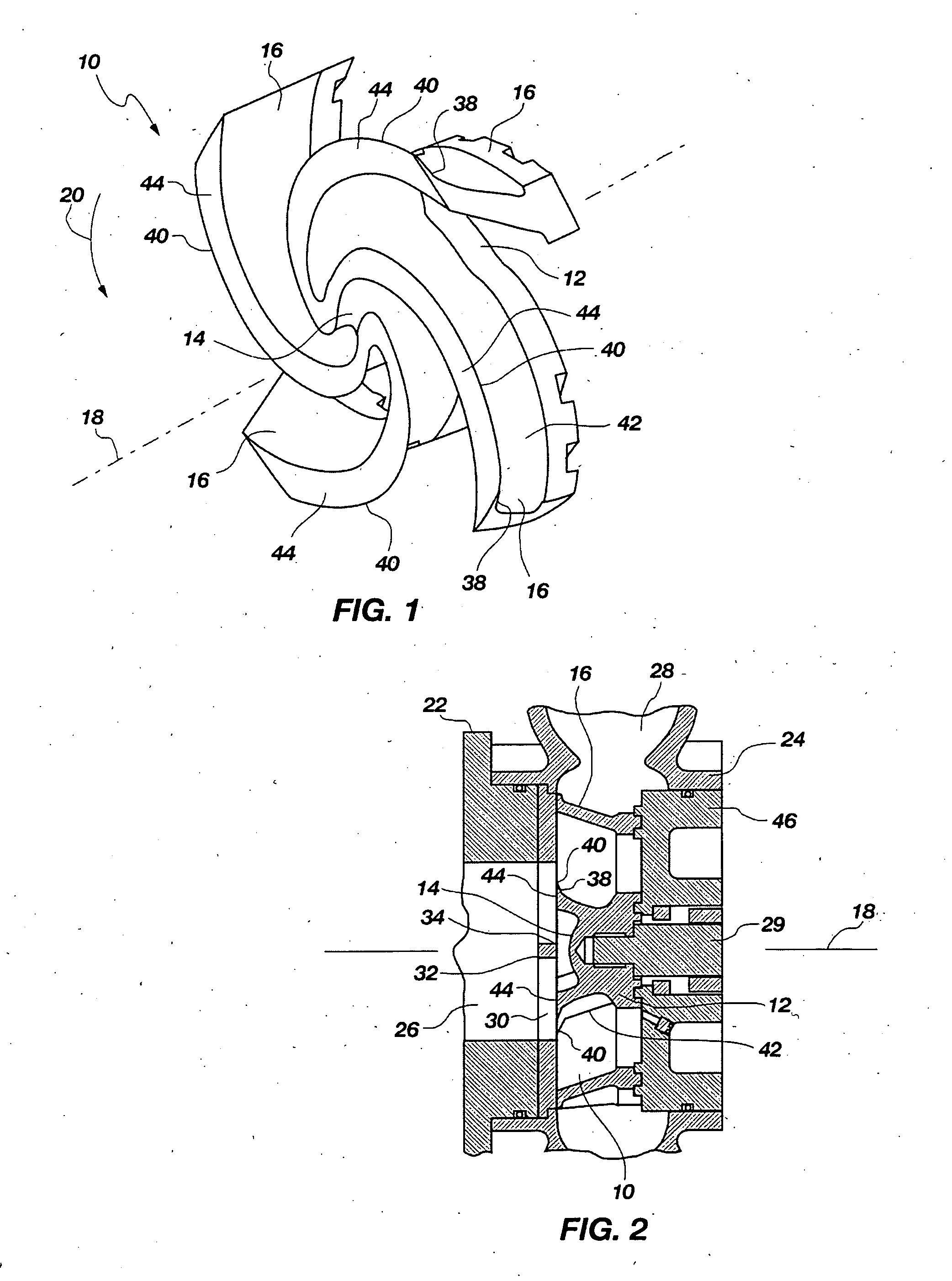
[0019]FIG. 1 illustrates an impeller 10 which incorporates the vane configuration of the present invention. In general, the impeller 10 is structured with a central hub 12 which provides means for securing the impeller 10 to the drive shaft of a pump. The impeller 10 is also configured with an eye 14 which is oriented toward the inlet of a pump to receive influent entering the pump. A plurality of vanes 16 extend radially outwardly from the central hub 12 of the impeller 10.

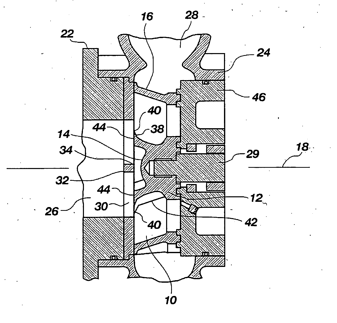
[0020]FIG. 2 depicts the position of the impeller 10 within a pump 22 to better illustrate the operational features of the impeller. The pump 22 conventionally comprises a pump casing 24 having an inlet 26 and an outlet 28. The impeller 10 is positioned within the pump casing 24 and is oriented to receive fluid entering through the pump inlet 26. The impeller 10 is also oriented relative to the pump outlet 28 to expel fluid and entrained solids outwardly toward the pump outlet 28. The hub 12 of the impeller 10 i...


PUM


Abstract

A pump impeller for use in industrial pumps of the centrifugal type is disclosed in which the vanes of the pump impeller are particularly configured to maintain pumping efficiency as the vane wears over continuous use or operation of the pump. The impeller vane is configured to continuously present an aggressive cutting surface at the leading edge of the vane even though the vane may become degraded and worn through continuous use.

Description

CROSS-REFERENCE TO RELATED APPLICATION [0001] This application is a non-provisional application claiming priority to provisional patent application Ser. No. 60 / 483,964 filed Jul. 1, 2003.BACKGROUND OF THE INVENTION [0002] 1. Field of the Invention [0003] This invention relates to centrifugal pumps, particularly of the chopper type, and specifically relates to an impeller vane configuration particularly suited for use in a chopper pump. [0004] 2. Description of Related Art [0005] Various industries involve or require the processing of solid waste material into a form that can be disposed of in a suitable manner. Certain solid wastes containing or comprising, for example, plastics, metals, animal byproducts and other hard or stringy materials present a particular challenge to processing that material into a disposable form. Therefore, centrifugal pumps of the type known as chopper pumps are typically employed in processing such solid waste material into a reduced size that can be disp...

Claims


Application Information

Patent Timeline
Patent Type & Authority Applications(United States)
IPC IPC(8): B63H1/16F04DF04D29/22F04D29/30
CPCF04D29/2288F04D7/045F04D29/242
Inventor SHAW, JAMES G.
Owner ENVIROTECH PUMPSYSTEMS INC
Why Eureka
Try Eureka