

Adjustable threshold assembly
- Summary
- Abstract
- Description
- Claims
- Application Information
AI Technical Summary
Benefits of technology
Problems solved by technology
Method used
Image

Examples
Embodiment Construction
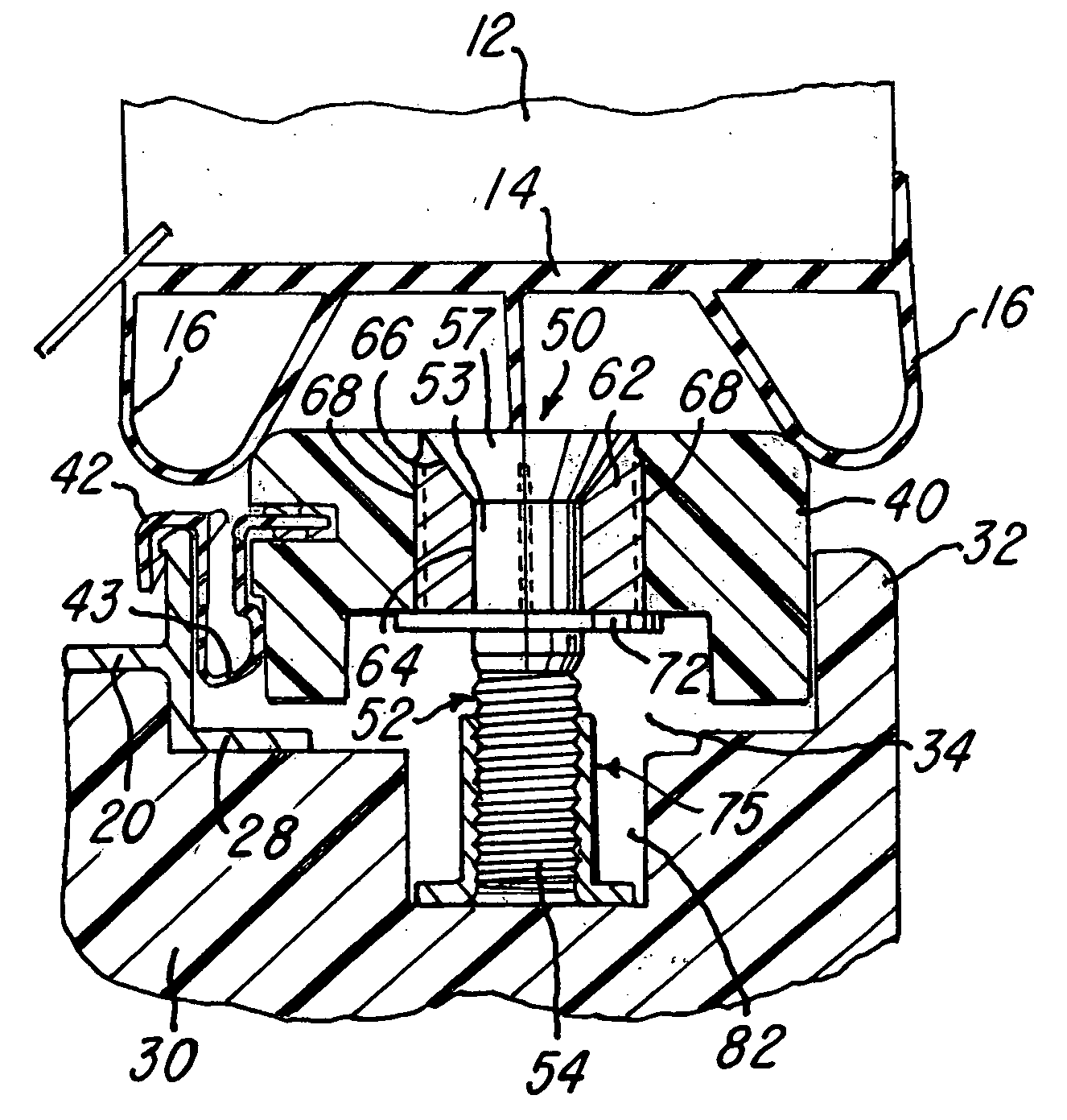
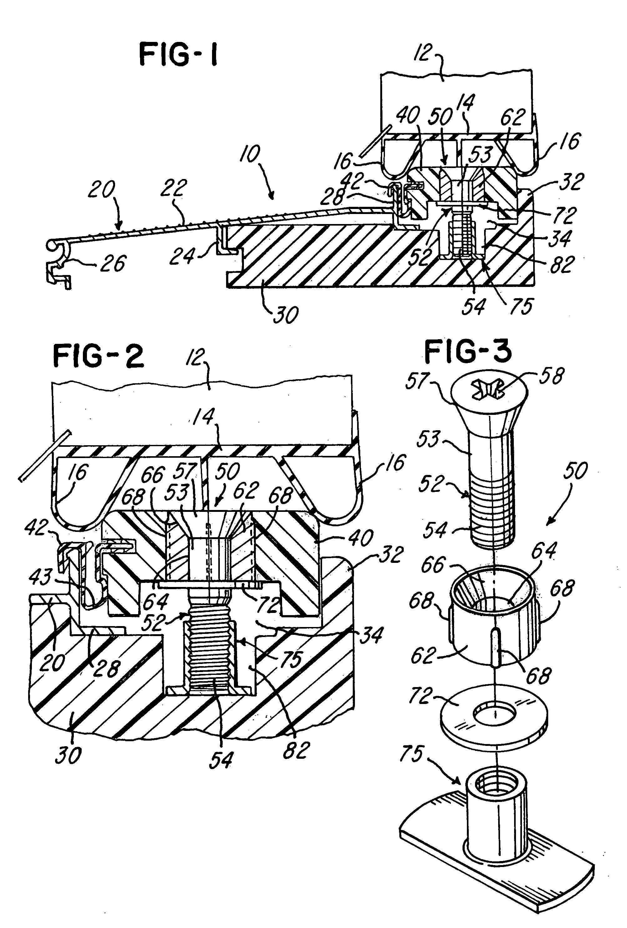
[0009]FIG. 1 illustrates a threshold or threshold assembly 10 which is constructed similar to the threshold assembly disclosed in the above-mentioned patents and which extends at the bottom of a rectangular frame (not shown) supporting a movable or swinging door 12. The door has a bottom surface which carries weather stripping sweep or a sealing strip 14 which is preferably extruded of a plastics or rubber material and has resilient and flexible downwardly projecting edge portions 16. The threshold assembly 10 includes an extruded aluminum sill member 20 which has a generally flat and sloping top wall 22, a downwardly projecting L-shaped intermediate flange 24 and an outer flange 26 which may also be used for attaching an extruded aluminum sill extension strip or member (not shown). The aluminum sill member 20 also includes an L-shaped flange or end portion 28 which seats on a base member 30 formed of wood or a plastics material or a composite material, and the base member hooks ont...
PUM
 Abstract
Description
Claims
Application Information