Objective lens driving apparatus

Inactive Publication Date: 2005-05-03
MITSUBISHI ELECTRIC CORP
View PDF22 Cites 3 Cited by
  • Summary
  • Abstract
  • Description
  • Claims
  • Application Information

AI Technical Summary

Benefits of technology

[0013]With such an arrangement, the objective lens can be driven in the focusing direction and in the tracking direction by one kind of magnet, and therefore the number of components can be reduced. Additionally, the magnet having a complicated structure is eliminated, and therefore the cost of the component can be reduced. Accordingly, the manufactu

Problems solved by technology

Moreover, the backlash of the lens holder can be restricted by the magnetic force generated by the urging member and

Method used


Image

  • Objective lens driving apparatus
  • Objective lens driving apparatus
  • Objective lens driving apparatus

Examples


Example

Embodiment 1

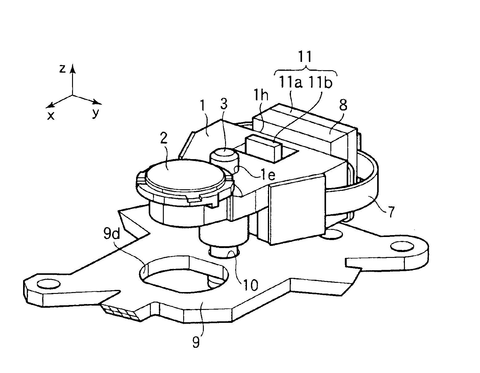
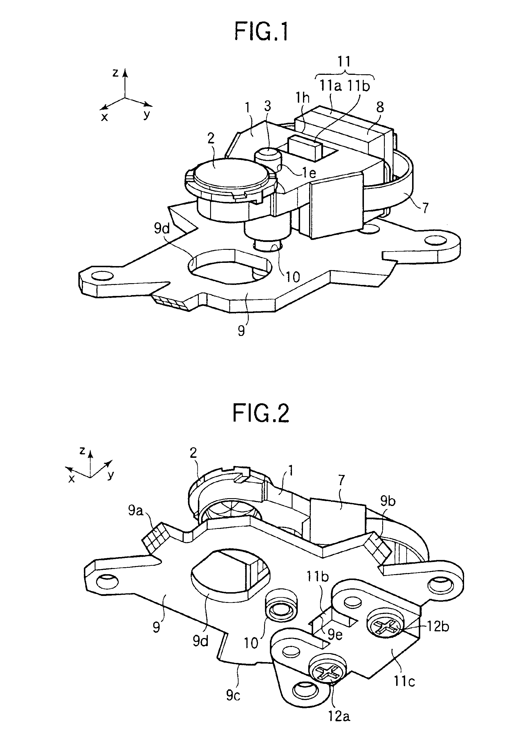
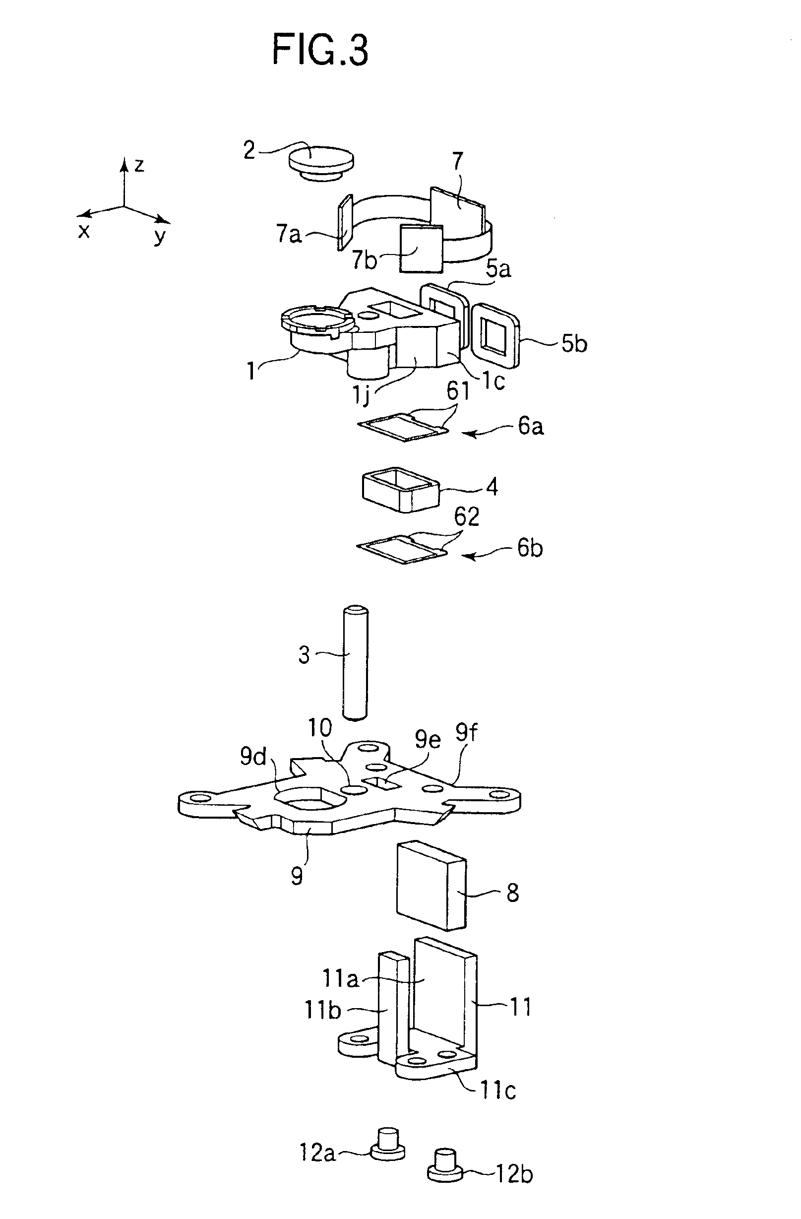
[0035]FIGS. 1 and 2 are front perspective views of an objective lens driving apparatus according to Embodiment 1 of the present invention, respectively seen from above and seen from below. FIG. 3 is an exploded perspective view of the objective lens driving apparatus according to Embodiment 1. FIG. 4 is a front perspective view of a movable part of the objective lens driving apparatus, seen from below. The objective lens driving apparatus according to Embodiment 1 is mounted to an optical disk drive device (not shown), and includes a lens holder 1 that holds an objective lens 2 and a stationary base (a stationary part) 9 that supports the lens holder 1, as shown in FIG. 1. The lens holder 1 holds the objective lens 2 in such a manner that the direction of the optical axis (z-direction) of the objective lens 2 is perpendicular to the recording surface of the recording media. In the description below, y-direction is used to mean the direction traversing the track of the re...

Example

Embodiment 2

[0058]FIG. 6 is a front perspective view of an objective lens driving apparatus according to Embodiment 2, seen from above. FIG. 7 is a front perspective view of a movable part of the objective lens driving apparatus according to Embodiment 2, seen from below. FIG. 8 is an exploded perspective view of the objective lens driving apparatus according to Embodiment 2. In FIGS. 6 to 8, the components that are the same as or correspond to the components shown in FIGS. 1 to 3 are assigned the same reference numerals. As shown in FIG. 6, the structure of the lens holder 1 of Embodiment 2 is different from that of Embodiment 1. The structures of the stationary base 9 and the stationary yoke 11 are the same as those of Embodiment 1.

[0059]As shown in FIG. 7, the lens holder 1 has a generally elongated plate portion 1a having a lens mounting portion 1g formed at an end in the longitudinal direction thereof, as in Embodiment 1. Wall portions 1c are formed on both side ends of the pla...

Example

Embodiment 3

[0063]FIG. 9 is a rear perspective view of an objective lens driving apparatus according to Embodiment 3, seen from above. FIG. 10 is a front perspective view of a stationary base according to Embodiment 3, seen from above. FIG. 11 is a front perspective view of a stationary part including the stationary base shown in FIG. 10, seen from above. In FIGS. 9 to 11, the components that are the same as or correspond to the components shown in FIGS. 1 to 3 are assigned the same reference numerals.

[0064]In Embodiments 1 and 2 described above, the stationary base 9 and the stationary yoke 11 are separate with each other (FIG. 3). In contrast, in Embodiment 3, a stationary base 31 includes a part that functions as the stationary yoke, as shown in FIG. 9. The stationary base 31 shown in FIG. 10 is generally elongated and is made of magnetic material. A through hole 32 is formed in the stationary base 31, and is located at a center portion in the longitudinal direction of the statio...


PUM


Abstract

An objective lens driving apparatus includes a lens holder 1 that holds an objective lens 2, and a stationary base 9 that supports the lens holder 1 by a support shaft 3 parallel to an optical axis of the objective lens 2. A stationary yoke 11 and the magnet 8 are mounted to the stationary base 9. A focusing coil 4 and the tracking coils 5a and 5b are mounted to the lens holder 1. The interaction between the current in the focusing coil 4 and the magnetic field caused by the magnet 8 generates an electromagnetic force that moves the lens holder 1 along the support shaft 3. The interaction between the current in the tracking coils 5a and 5b and the magnetic field caused by the magnet 8 generates an electromagnetic force that rotates the lens holder 1 about the support shaft 3.

Description

[0001]This patent application is a divisional application of U.S. application Ser. No. 10 / 336,751 which was filed Jan. 6, 2003, which also claims priority based on a Japanese patent application No. 2002-75786 filed on Mar. 19, 2002, the contents of which are incorporated herein by reference.BACKGROUND OF THE INVENTION[0002]The present invention relates to an objective lens driving apparatus used in an optical data recording and reproducing apparatus or the like, for correcting a focusing error and a tracking error of a light spot formed on an optical data recording media such as an optical disk.[0003]In the optical data recording and reproducing apparatus or the like, the data is recorded on and / or reproduced from the optical data recoding media (hereinafter, referred to as a recording media) such as the optical disk. In order to record the data on and / or reproduce the data from the recording media, the focus of an objective lens must be adjusted on a groove or a pit in which the da...

Claims


Application Information

Patent Timeline
IPC IPC(8): G11B7/09
CPCG11B7/0935G11B7/0933
Inventor NAKAMURA, KEIJIYABE, MITORU
Owner MITSUBISHI ELECTRIC CORP
Why Eureka
Try Eureka