Power source connection device and low-temperature showcase including the same

Active Publication Date: 2007-11-22
SANYO ELECTRIC CO LTD
View PDF18 Cites 6 Cited by
  • Summary
  • Abstract
  • Description
  • Claims
  • Application Information

AI Technical Summary

Benefits of technology

[0019]Furthermore, according to the third invention, in the above invention, the outer peripheral surface of the electrode portion of the power source socket or the inner peripheral surface of the peripheral wall portion of the power source plug is provided with the seal material which seals between the peripheral wall portion and the electrode portion. Therefore, the engagement between the engaging portion formed on the outer surface of the peripheral wall portion of the power source plug and the engaged portion formed on the inner surface of the outer peripheral wall of the power source socket is not interfered. Since the seal material is arranged on the peripheral wall portion of the power source socket or the inner peripheral surface of the peripheral wall portion of the power source plug, it is possible to suppress a disadvantage that humidity or dew condensation water enters even a connecting portion between the electrode portion and the terminal. In consequence, it is possible to prevent a disadvantage that power leakage or the like is caused by entrance of the dew condensation water or the like.
[0020]In addition, according to the fourth invention, in the above inventions, the outer peripheral wall of the power source socket is formed into the double structure having the hollow inner portion. Therefore, even when the outer peripheral wall of the power source socket is attached to the low-temperature showcase at a position on a cold-air duct side, the inside of the power source socket can be insulated by the double structure. As compared with a conventional power source socket structure, it is possible to suppress a disadvantage that the dew condensation water is generated in the power source socket or the electrode portion connected to the power source plug.
[0021]In consequence, an amount of the dew condensation w

Problems solved by technology

Therefore, the power source socket which is not connected to the power source plug has a problem that, when an in-chamber temperature drops to generate dew condensation water, this dew condensation water enters the electrode portion formed at the power source socket to cause power leakage.
There is also a problem that, when ice gradually grows, the power source plug drops down from the power source socket.
Once the dew condensation water enters between the power source socket and the power source plug to generate the frost, it is difficult to securely attach the power source plug to the power source socket until the frost is removed.
However, in such a structure, when the power source plug is attached to the power source socket, it can

Method used


Image

  • Power source connection device and low-temperature showcase including the same
  • Power source connection device and low-temperature showcase including the same
  • Power source connection device and low-temperature showcase including the same

Examples


Embodiment Construction

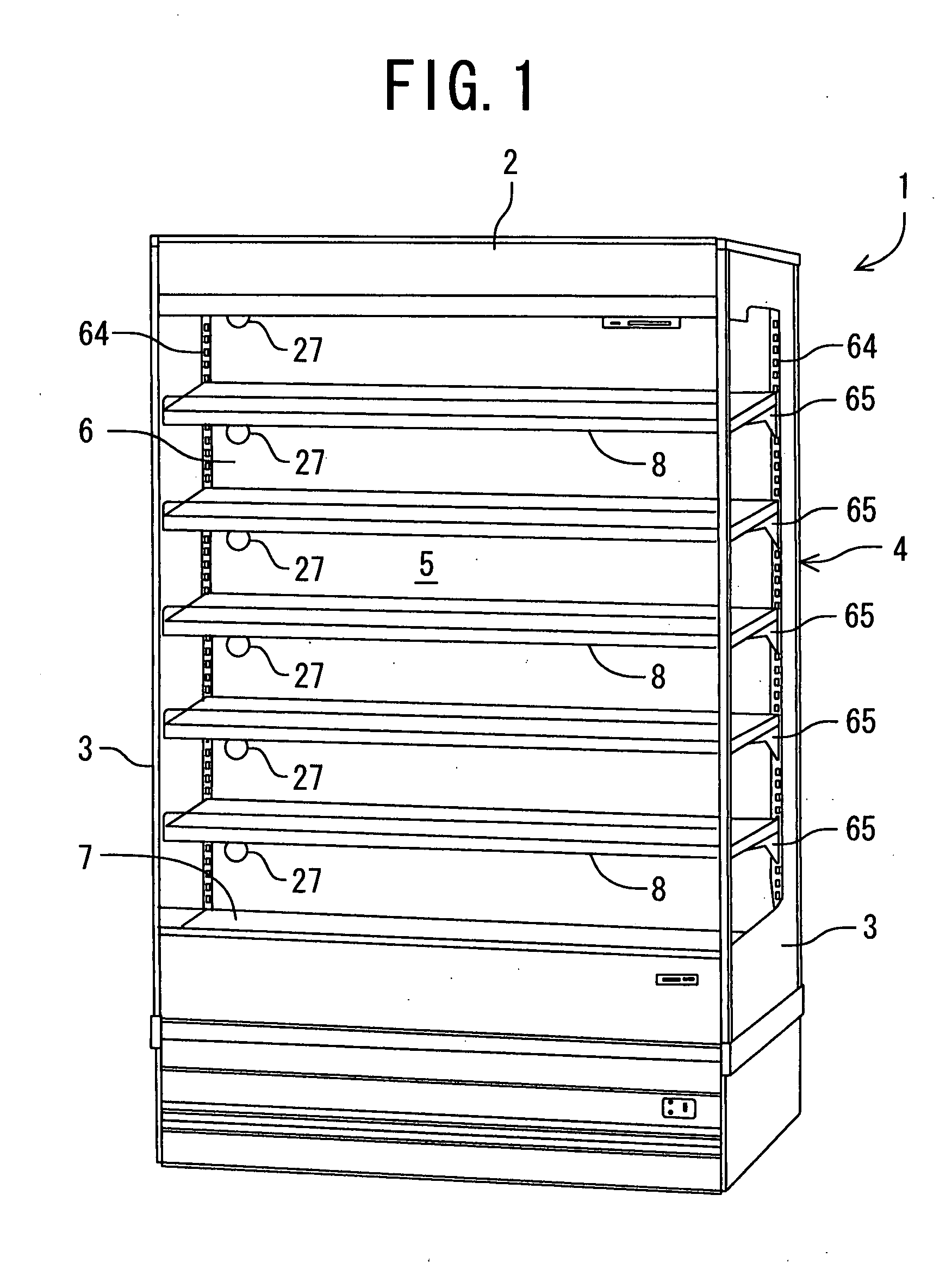
[0037]A low-temperature showcase 1 to which the present invention is applied will hereinafter be described with reference to the drawings.

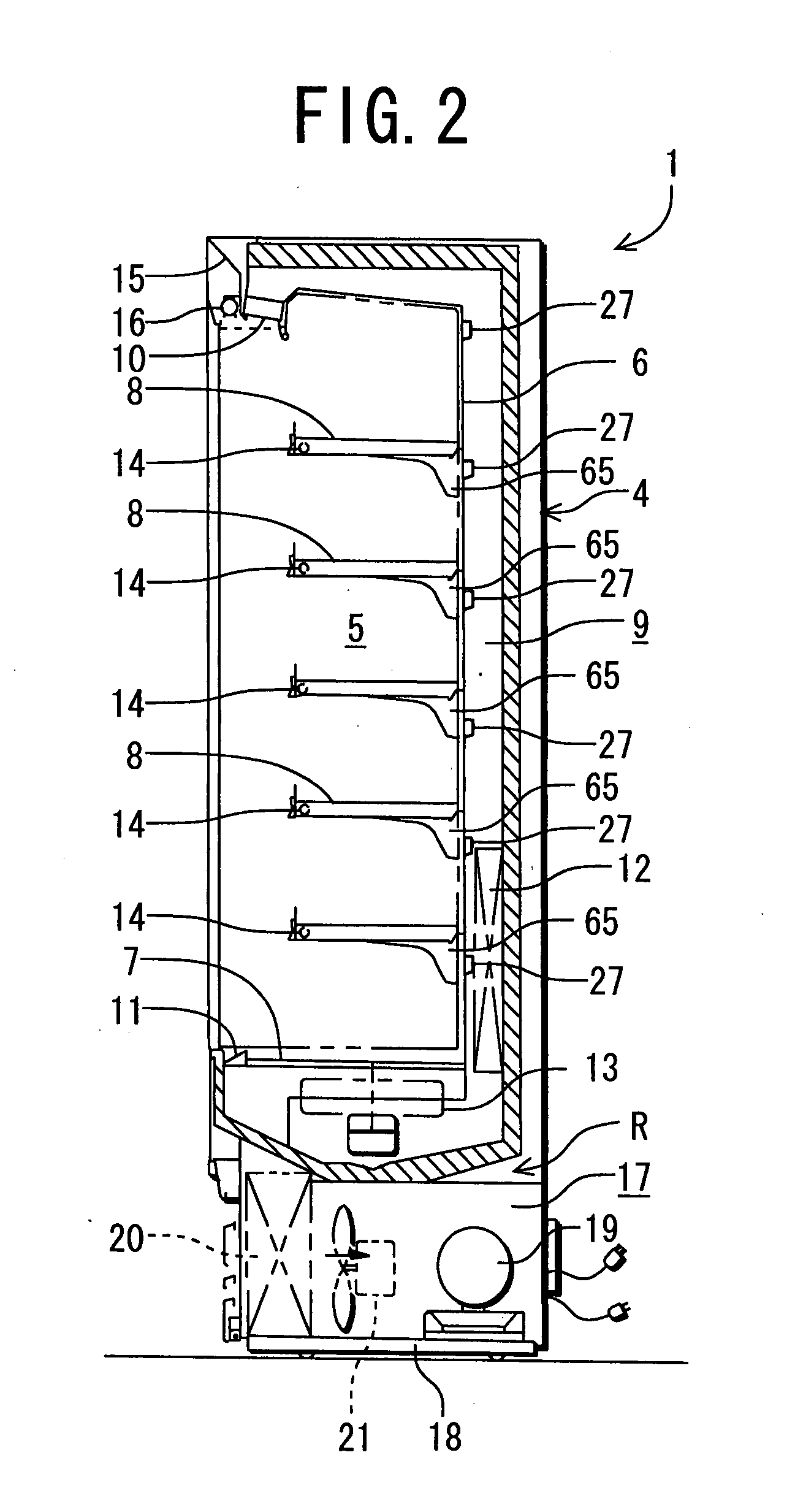
[0038]FIG. 1 is a perspective view of the low-temperature showcase 1 to which the present invention is applied, and FIG. 2 is a schematic vertical side view of the low-temperature showcase 1. The low-temperature showcase 1 is installed in a store such as a supermarket or a convenience store, and side plates 3, 3 are attached to opposite sides of an insulating wall 2 having a substantially U-shaped sectional shape to constitute a main body 4. A partition plate 6 and a bottom plate 7 are attached at an interval from an inner part of the insulating wall 2. On an inner side of these plates, a showroom 5 which opens to a front surface is constituted. Moreover, a series of cold-air ducts 9 are constituted between these plates and room and the insulating wall 2.

[0039]Moreover, this duct 9 communicates with a discharge port 10 which opens at an upper edge...


PUM


Abstract

An object of the present invention is to provide a power source connection device capable of avoiding a disadvantage that a power source plug drops down from a power source socket owing to frost which has grown on the power source socket itself, the power source connection device comprises a power source socket attached to a partition plate which separates a showroom of a low-temperature showcase and a cold-air duct from each other; and a power source plug connected to the power source socket, the power source socket has a vessel-like attachment base and an electrode portion formed so as to protrude at a predetermined interval from an inner portion of an outer peripheral wall constituting the attachment base, the power source plug has a terminal for the power source to be electrically connected to the electrode portion and a peripheral wall portion which encloses the terminal and the like, and the power source plug is detachably engaged with the power source socket in a state in which the terminal and the like are connected to the electrode portion of the power source socket.

Description

BACKGROUND OF THE INVENTION[0001]The present invention relates to a power source connection device of a showcase which supplies power to a fluorescent lamp and the like.[0002]In general, a showcase or the like is provided with a power source connection device including a power source socket connected to the inside of a chamber of a main body of the showcase and a power source plug which is inserted into this power source socket to supply power to a fluorescent lamp and the like. In a conventional power source connection device described in, for example, Japanese Patent Application Laid-Open No. 11-273775, the power source socket is provided with a peripheral wall at an outer periphery thereof, and a recessed portion in which an electrode portion is formed at an inner portion of the peripheral wall. This electrode portion is provided with an insertion port for the power source. On the other hand, the power source plug includes a movable portion which is connected to a wiring line ext...

Claims


Application Information

Patent Timeline
IPC IPC(8): F21V15/00
CPCH01R13/50H01R13/52H01R13/521H01R13/73H01R13/533H01R13/627H01R13/5213
Inventor OKETANI, TETSUYAMATSUZAWA, SHIGEO
Owner SANYO ELECTRIC CO LTD
Why Eureka
Try Eureka