Parallel hybrid vehicle

Active Publication Date: 2020-06-04
KAWASAKI MOTORS LTD
View PDF0 Cites 2 Cited by
  • Summary
  • Abstract
  • Description
  • Claims
  • Application Information

AI Technical Summary

Benefits of technology

[0005]It is an object of the present disclosure to ensure the maintenance of the function of a water pump in a parallel hybrid vehicle and at the same

Problems solved by technology

However, with a conventional configuration in which the engine is connected to a water pump for circulation of a cooling liquid, the function of the water pump may be lost upon stoppage of the engine.
With the configuration of Pat

Method used


Image

  • Parallel hybrid vehicle
  • Parallel hybrid vehicle
  • Parallel hybrid vehicle

Examples


Example

First Embodiment

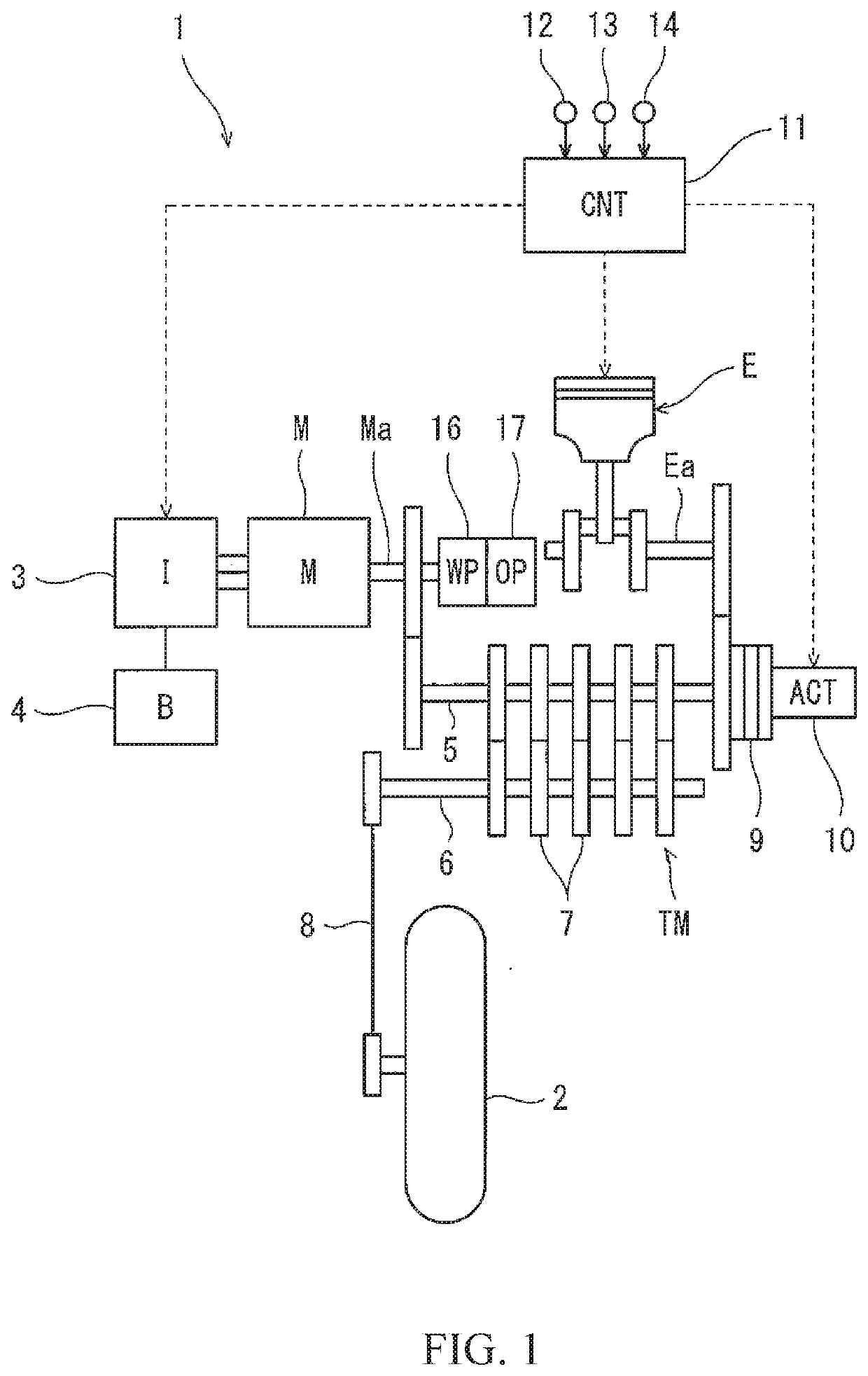
[0028]FIG. 1 is a configuration diagram of a parallel hybrid vehicle 1 according to a first embodiment. As shown in FIG. 1, the vehicle 1 is, for example, a motorcycle. The vehicle 1 includes an unillustrated driven wheel (front wheel) and a drive wheel 2 (rear wheel). The vehicle 1 includes an engine E and an electric motor M. The engine E and electric motor M are disposed between the front wheel (driven wheel) and rear wheel (drive wheel 2).

[0029]The engine E is an internal combustion engine. The engine E serves as a drive source for travel which drives the drive wheel 2. The engine E serves also as an electricity generator drive source. The engine E is, for example, a four-stroke engine.

[0030]The electric motor M generates power from electricity supplied from a battery 4 via an inverter 3, thus serving as a drive source for travel which drives the drive wheel 2. The electric motor M generates electricity from power transmitted from an input shaft 5 of a transmissi...

Example

Second Embodiment

[0047]FIG. 5 is a configuration diagram of a parallel hybrid vehicle 101 according to a second embodiment. In the parallel hybrid vehicle 101 of the second embodiment, as seen from FIG. 5, the water pump 16 is disposed in a different way. In the parallel hybrid vehicle 101, the drive shaft of the water pump 16 is disposed coaxially with, and coupled to, the input shaft 5 of the transmission TM. The drive shaft of the oil pump 17 is disposed coaxially with, and coupled to, the rotation shaft Ma of the electric motor M. With this configuration, as in the first embodiment, the water pump 16 and oil pump 17 can be driven irrespective of the travel mode and without the need for providing an auxiliary motor dedicated for driving of the water pump 16 and oil pump 17. The other elements are the same as those of the first embodiment described above. The same elements are denoted by the same reference signs and will not be described again.

Example

Third Embodiment

[0048]FIG. 6 is a configuration diagram of a parallel hybrid vehicle 201 according to a third embodiment. In the parallel hybrid vehicle 201 of the third embodiment, as shown in FIG. 6, the drive shaft of the water pump 16 is coupled to the crankshaft Ea of the engine E via a first one-way clutch 261. The first one-way clutch 261 permits transmission of power from the crankshaft Ea of the engine E to the water pump 16, and prohibits transmission of power from the water pump 16 to the crankshaft Ea of the engine E.

[0049]The drive shaft of the water pump 16 is coupled to the rotation shaft Ma of the electric motor M via a second one-way clutch 262. The second one-way clutch 262 permits transmission of power from the rotation shaft Ma of the electric motor M to the water pump 16, and prohibits transmission of power from the water pump 16 to the rotation shaft Ma of the electric motor M. The drive shaft of the oil pump 17 is coupled to the drive shaft of the water pump 1...


PUM


Abstract

A parallel hybrid vehicle includes: an engine serving as a drive source for travel of the parallel hybrid vehicle; an electric motor serving as a drive source for travel of the parallel hybrid vehicle; and a water pump that causes a cooling liquid to circulate in a cooling path. The water pump is connected to the engine to receive power from the engine and is connected to the electric motor to receive power from the electric motor.

Description

CROSS-REFERENCE TO RELATED APPLICATION[0001]This application claims priority to and the benefit of Japanese Patent Application No. 2018-227335, filed on Dec. 4, 2018, the entire disclosure of which is incorporated herein by reference.BACKGROUND OF THE INVENTIONField of the Invention[0002]The present disclosure relates to a parallel hybrid vehicle including a water pump.Description of the Related Art[0003]A parallel hybrid vehicle is known which includes an engine and an electric motor as drive sources for travel of the vehicle, the engine and electric motor being coupled to a drive wheel to transmit power to the drive wheel (see Japanese Laid-Open Patent Application Publication No. H10-339185, for example). In such a hybrid vehicle, components such as the engine, the electric motor, and an inverter heat up, and these components need to be cooled. However, with a conventional configuration in which the engine is connected to a water pump for circulation of a cooling liquid, the funct...

Claims


Application Information

Patent Timeline
IPC IPC(8): F01P7/14B60W10/30B60K6/485
CPCF01P2050/24F01P7/14B60W10/30F01P2070/10B60K6/485B60K6/48B60K2006/4825B60K6/387B60K6/383B60K6/40B60K6/547B60W2300/36Y02T10/62F01P2005/125F01P5/12F01P7/042
Inventor MATSUDA, YOSHIMOTO
Owner KAWASAKI MOTORS LTD
Why Eureka
Try Eureka