
Refrigerator

a technology of refrigerator and freezer, which is applied in the field of refrigerators, can solve the problems of inefficient use of the entire received space of the freezing chamber, and achieve the effects of maximizing the available received space, efficient volume of the refrigerator, and increasing the utility of the refrigerator and the convenience of users

Active Publication Date: 2005-10-06
LG ELECTRONICS INC
View PDF16 Cites 26 Cited by
  • Summary
  • Abstract
  • Description
  • Claims
  • Application Information

AI Technical Summary

Benefits of technology

[0017] Therefore, an objective of the present invention is to maximize usefulness of a refrigerator by disposing an evaporator unit in a space other than a predetermined space of a freezing chamber or a cooling chamber.
[0022] Therefore, the refrigerator having the evaporator in the compartment for partitioning the freezing chamber and the cooling chamber from each other can increase utility of the refrigerator and convenience of the user compared to that of the same size by maximizing availability of the received space as the efficient volume of the refrigerator.

Problems solved by technology

Nevertheless, the extra space is not used, so that the entire received space of the freezing chamber is not efficiently used.

Method used


Image

  • Refrigerator
  • Refrigerator
  • Refrigerator

Examples


first embodiment

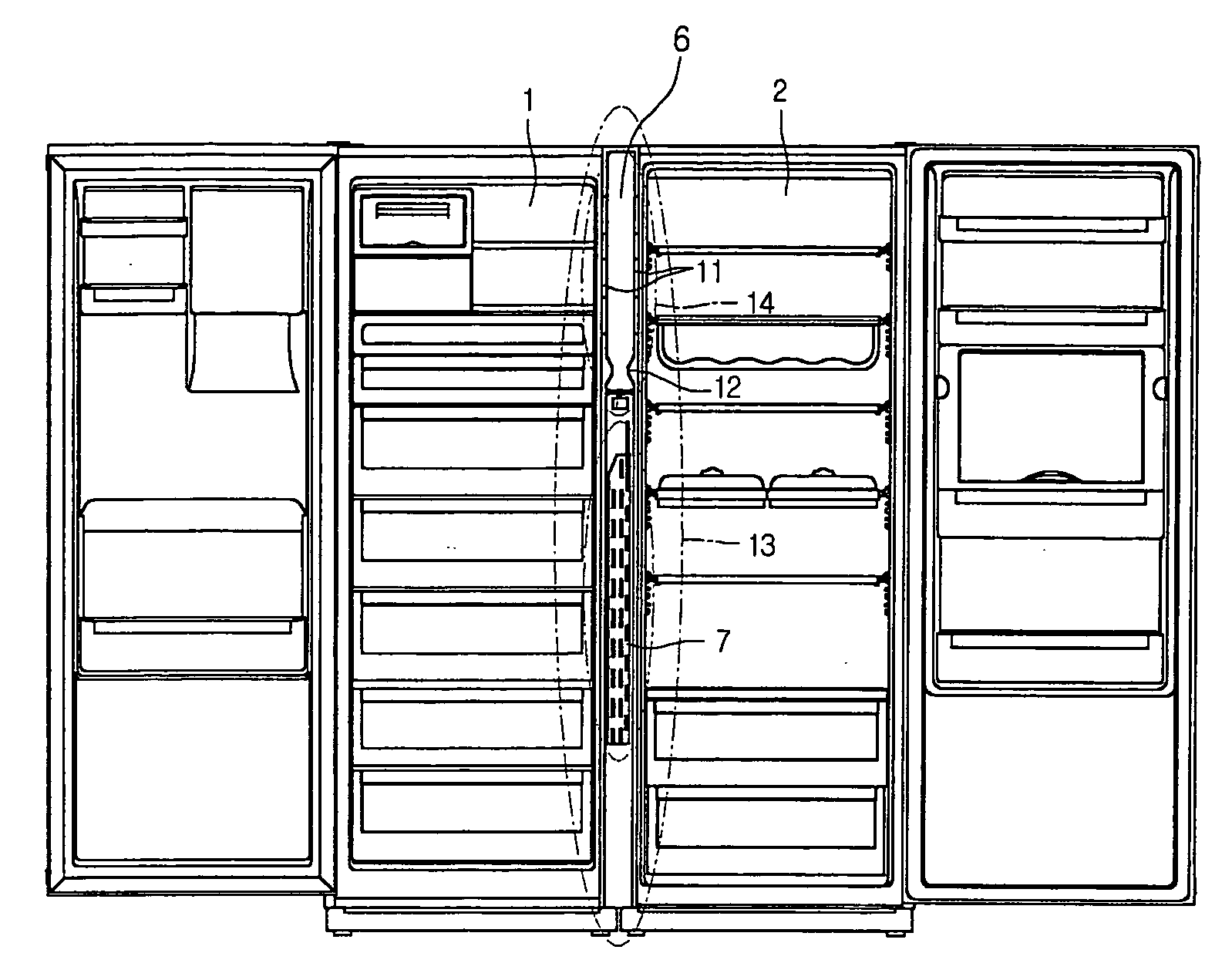
[0041]FIG. 7 shows a refrigerator having the evaporator, the blow fan and the cooling air outlet of FIG. 5.

[0042] The evaporator 7 of the evaporator unit 13 is provided in the space 6 between the freezing chamber 1 and the cooling chamber 2. The means 14, such as the blow fan and the cooling air outlet 11, for guiding and controlling the cooling air passing through the evaporator to the freezing chamber and the cooling chamber is provided

[0043] The evaporator may be mounted around the middle portion of the compartment.

second embodiment

[0044]FIG. 8 shows a refrigerator having the evaporator, the blow fan and the cooling air outlet of FIG. 5. The evaporator can be provided on a lower portion of the compartment.

third embodiment

[0045]FIG. 9 shows a refrigerator having the evaporator, the blow fan and the cooling air outlet of FIG. 5. The path between the side walls, as the passage of the cooling air, for transmitting the cooling air passing through the blow fan to the cooling air outlet is uniformly formed.

[0046] As can be seen from the foregoing refrigerator composed of the freezing chamber and the cooling chamber, the evaporator unit is provided in the means for partitioning the freezing chamber and the cooling chamber from each other, so that it is possible to maximize availability of the received space as the efficient volume of the refrigerator. Eventually, the utility of the refrigerator is increased compared to that of the same size, and simultaneously it is possible to increase convenience of the user.

[0047] While the preferred embodiments of the present invention have been described, the present invention may be employed to various changes, modifications and their equivalents. Thus, it is apparen...


PUM


Abstract

Disclosed is a refrigerator with a freezing chamber and a cooling chamber, in which an evaporating unit is provided in a means for partitioning between the freezing chamber and the cooling chamber. The refrigerator comprises of freezing and cooling chambers, each of the freezing and cooling chambers being provided with at least one received space; an evaporator; and a means for transmitting and controlling a cooling air heat-exchanged with the evaporator toward at least one place in the freezing and cooling chambers, wherein a means for partitioning the freezing and cooling chambers from each other has a predetermined space therein, the predetermined space is provided with the evaporator and at least one means for transmitting and controlling the cooling air.

Description

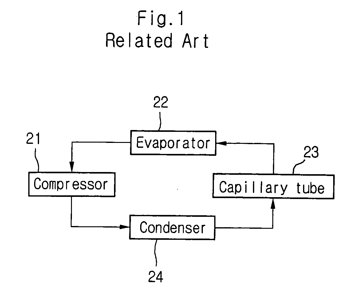
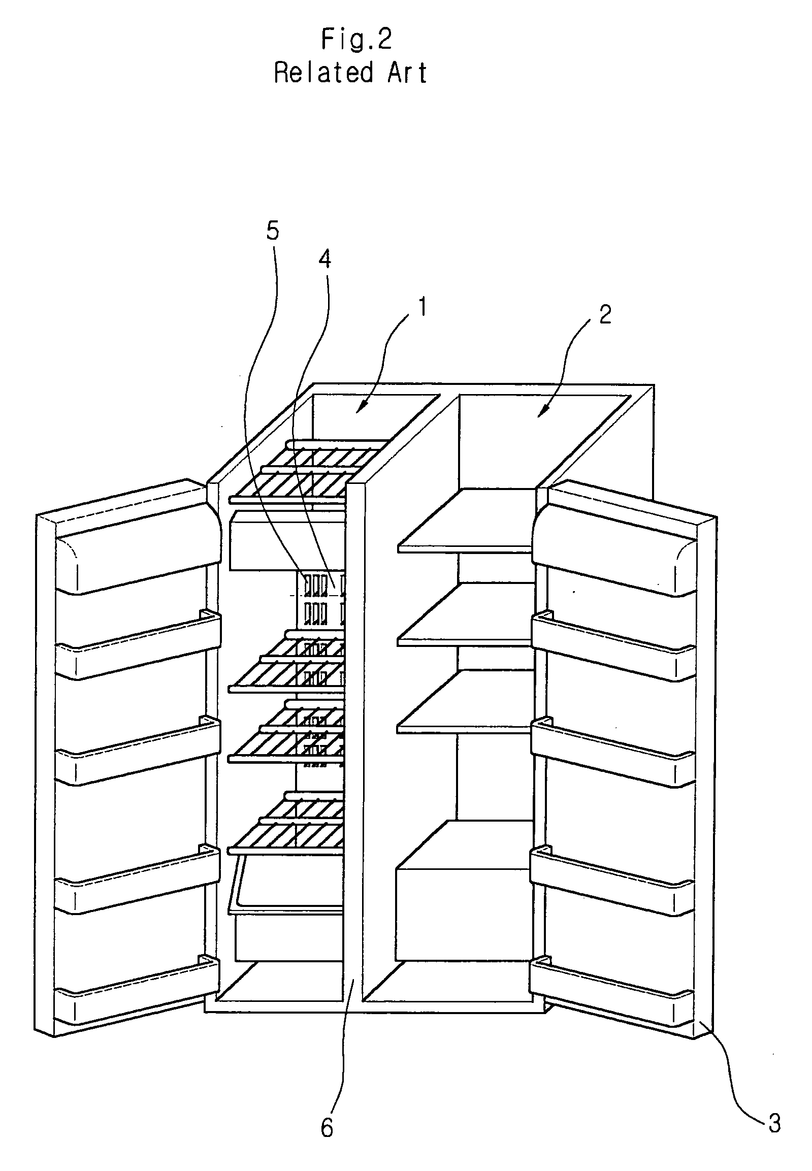
BACKGROUND OF THE INVENTION [0001] 1) Field of the Invention [0002] The invention relates to a refrigerator constituting a freezing chamber and a cooling chamber, in which an evaporating unit is provided in a means for partitioning between the freezing chamber and the cooling chamber. [0003] 2) Description of the Related Art [0004] A conventional refrigerator is generally configured of two chambers, a freezing chamber and a cooling chamber, which are vertically separated from each other. A current refrigerator is gradually changed into a structure capable of opening / closing the freezing and cooling chamber at the front. [0005]FIG. 1 is a block diagram showing a freezing cycle of a general refrigerator. [0006] As shown in FIG. 1, a refrigerant compressed by a compressor 21 enters a condenser 24. The refrigerant passing through the condenser 24 enters a capillary tube 23. The refrigerant passing through the capillary tube 23 enters an evaporator 24 to generate a freezing effect, and t...

Claims


Application Information

Patent Timeline
Patent Type & Authority Applications(United States)
IPC IPC(8): A47F3/04F25D11/02F25D17/04F25D17/06F25D23/06
CPCF25D17/045F25D17/065F25D23/061F25D2400/06F25D2317/0664F25D2317/067F25D2317/0672F25D2317/063
Inventor KIM, MOO YOULSEO, SANG HOLEE, DONG HOONYUN, YOUNG HOON
Owner LG ELECTRONICS INC
Learn More