Method and apparatus for measuring and orienting golf club shaft

a golf club shaft and orientation technology, applied in the field of measuring and orienting golf club shafts, can solve the problems of less consistent impact repeatability within the set, difficult to build a perfectly symmetrical golf club shaft, and more difficult for golfers to achieve the effect of quick and reliable determination of the preferred angular orientation

Inactive Publication Date: 2005-10-06
RICHARD M WEISS REVOCABLE TRUST U A D MAY 18 2001 +1
View PDF0 Cites 6 Cited by
  • Summary
  • Abstract
  • Description
  • Claims
  • Application Information

AI Technical Summary

Benefits of technology

[0011] It is an object of this invention to attempt to provide a method and apparatus for quickly and reliably determining the preferred angular orientation of a golf club shaft.

Problems solved by technology

Inconsistent bending or twisting makes it more difficult for the golfer to reproduce the downswing shaft bending or twisting from club to club, thereby resulting in less consistent impact repeatability within the set.
Golf club shaft manufacturers attempt to build shafts with symmetric stiffness to minimize inconsistent bending or twisting during the swing, but as a result of manufacturing limitations it is difficult to build a perfectly symmetric golf club shaft.
Therefore, substantially all golf club shafts exhibit some degree of asymmetry which results in some degree of inconsistent bending or twisting during the swing.
However, heretofore there has not been any convenient automated way to determine with consistency the parameters of a golf club shaft that would allow manufacturers or others to predict the performance of a golf club shaft.

Method used


Image

  • Method and apparatus for measuring and orienting golf club shaft
  • Method and apparatus for measuring and orienting golf club shaft
  • Method and apparatus for measuring and orienting golf club shaft

Examples


Embodiment Construction

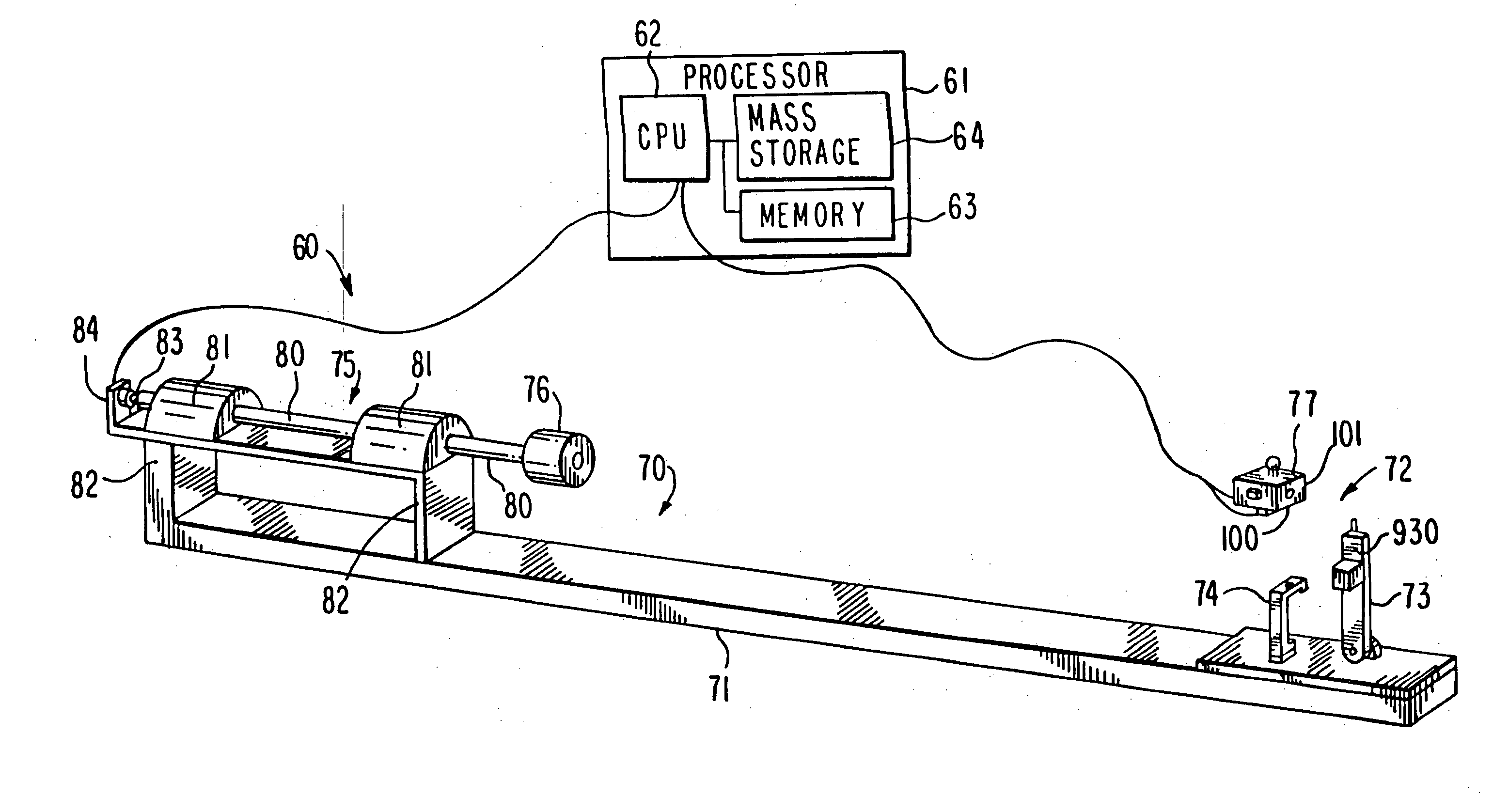
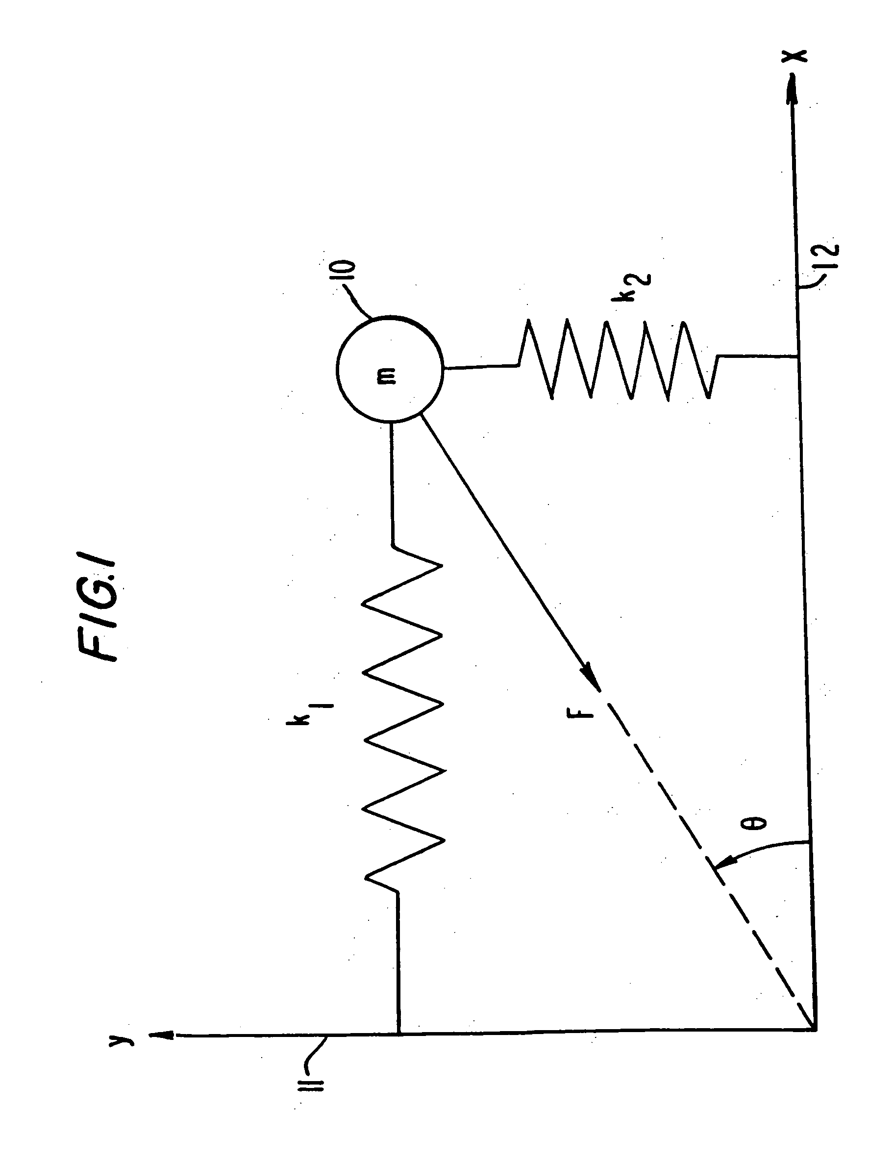
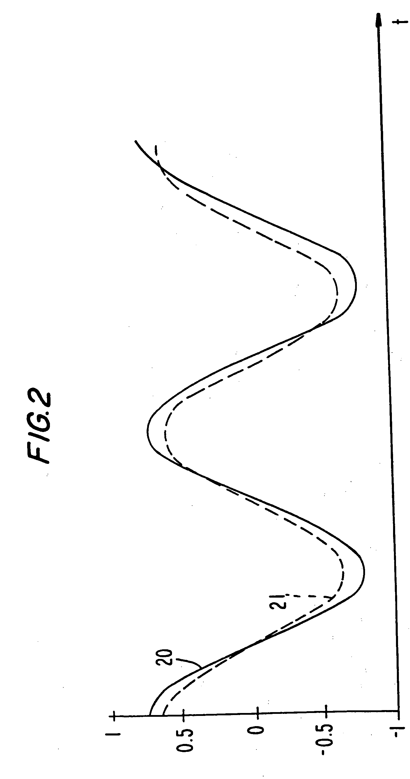
[0046] If a golf club shaft is immobilized at its handle end and displaced in a direction perpendicular to its longitudinal axis, then if the displacement direction lies in a planar oscillation plane of the shaft, the shaft will vibrate in that plane and, viewed end on, the distal tip of the shaft will oscillate back and forth along a line. For convenience, that line can be referred to as the x-axis. However, if the displacement direction is in a plane other than a planar oscillation plane, the distal tip of the shaft will vibrate in a motion having components along the x-axis as well as along an axis perpendicular to the x-axis, which for convenience can be referred to as the y-axis. This motion could be described as an “orbital” motion, although rather than tracing a single ellipse or other closed curve, the tip will move within an envelope such that, if the motion would not damp out (as it in reality does), it would be expected that the tip eventually would move through every poi...


PUM


Abstract

The preferred orientation, or planar oscillation plane, of a golf club shaft is located by measuring the oscillation of the shaft when an impulse is applied. Preferably, the out-of-plane oscillation is measured at a large number of angular positions about the shaft axis, and the principal planar oscillation plane is identified by that pair of opposed angular positions in which the out-of-plane oscillation is smallest. The location of the preferred orientation may be marked on the shaft and used to assemble a golf club with the planar oscillation plane in a predetermined orientation. The straightness of the shaft can also be determined by deriving its spring constant from its oscillation frequency and then measuring the restoring force when the shaft is deflected by the same nominal amount at different angular positions; differences in restoring force can be attributed to differences in actual deflection distance resulting from lack of straightness.

Description

CROSS REFERENCE TO RELATED APPLICATIONS [0001] This is a division of copending, commonly-assigned U.S. patent application Ser. No. 10 / 037,701, filed Nov. 9, 2001, now U.S. patent Ser. No. ______, which claims the benefit of U.S. Provisional Patent Applications Nos. 60 / 247,141 and 60 / 263,489, filed Nov. 10, 2000 and Jan. 22, 2001, respectively.BACKGROUND OF THE INVENTION [0002] This invention relates to measuring and orienting a golf club shaft. More particularly, this invention relates to a method and apparatus for automatically and reliably identifying the location of a planar oscillation plane, and particularly the principal planar oscillation plane, of a golf club shaft and for aligning that planar oscillation plane in a desired orientation, as well as for determining parameters of the golf club shaft, such as roundness, stiffness and straightness, that characterize golf club performance. [0003] When a golfer swings a golf club, the shaft of the golf club bends or twists, especia...

Claims


Application Information

Patent Timeline
Patent Type & Authority Applications(United States)
IPC IPC(8): A63B53/10A63B59/00G01H1/00G01H13/00
CPCA63B53/00A63B53/10A63B59/0074G01H13/00A63B2059/0003G01H1/00A63B2053/005A63B60/42A63B53/005A63B60/002A63B60/46
Inventor WEISSBUTLER, JOSEPH H.TWIGG, MICHAEL J.VOWELL, F. SHERRILLPALMER, LARRY R.
Owner RICHARD M WEISS REVOCABLE TRUST U A D MAY 18 2001
Why Eureka
Try Eureka