Mouse pad
a cushion and mouse technology, applied in the field of mouse pads, can solve the problems of cushioning not being able to secure the optimal support angle and the pain of the user's wris
- Summary
- Abstract
- Description
- Claims
- Application Information
AI Technical Summary
Benefits of technology
Problems solved by technology
Method used
Image

Examples
first embodiment
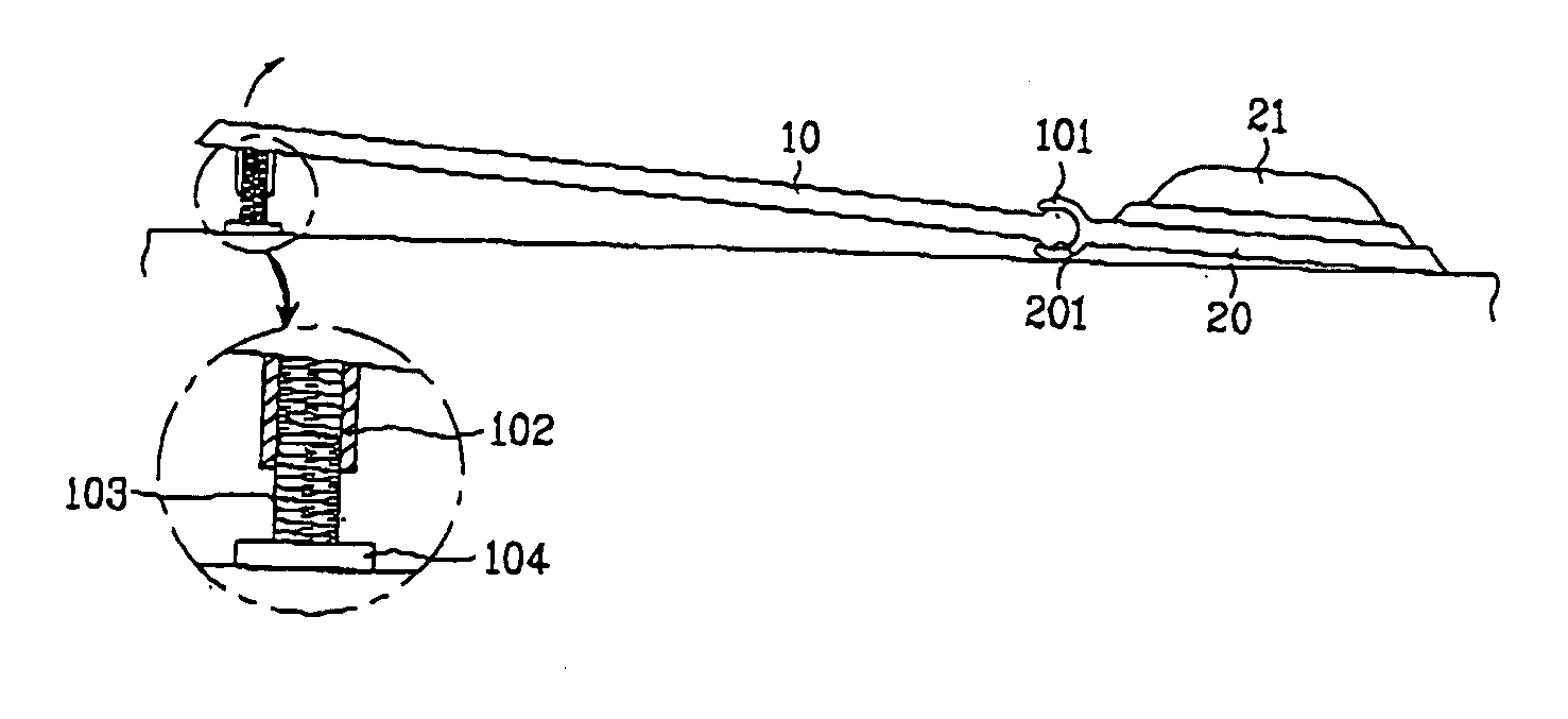
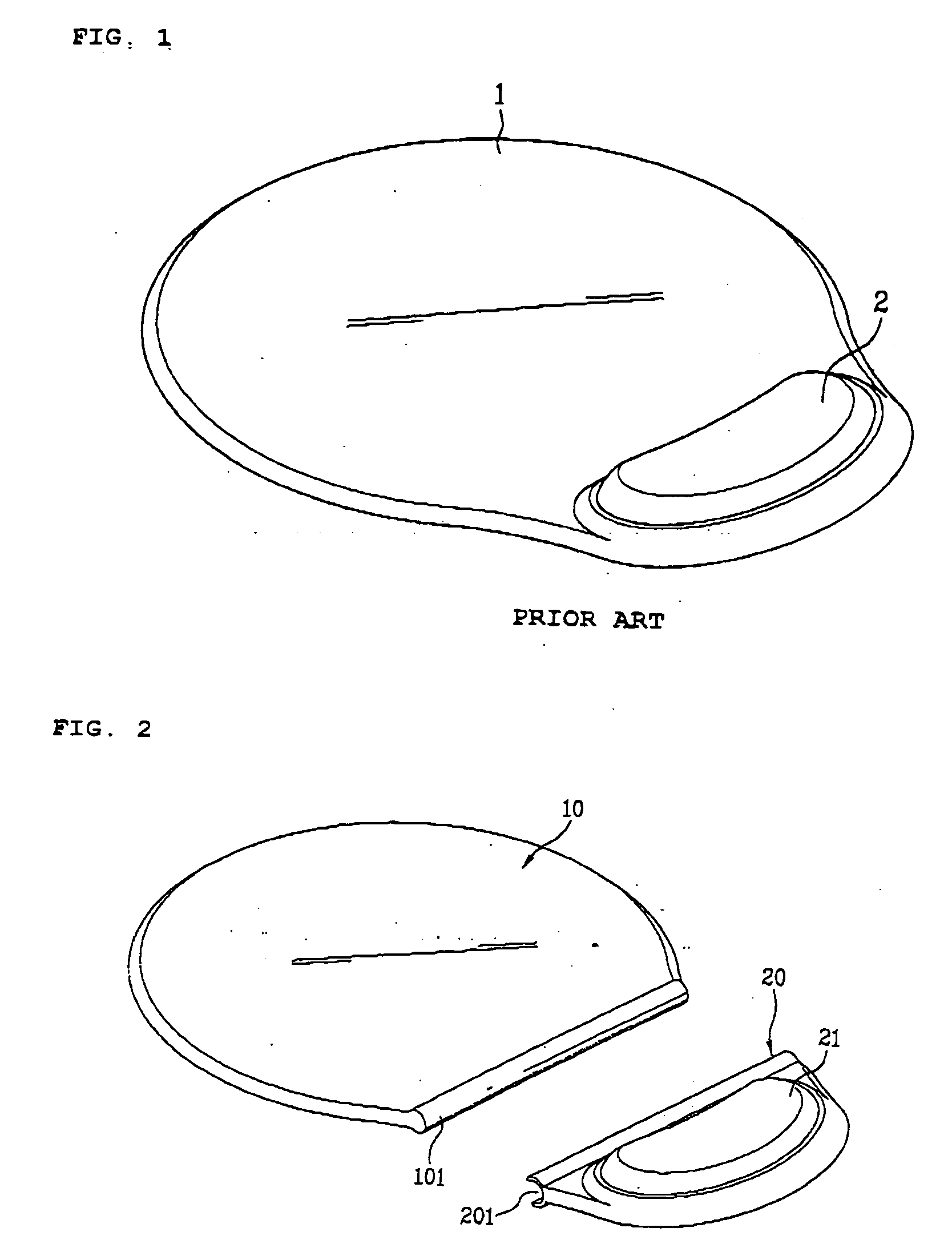
[0047]FIG. 2 and FIG. 3 illustrate a mouse pad according to a first embodiment of the present invention. A mouse pad, as shown in FIG. 2 and FIG. 3, includes a pad part 10 having a flat plate shape on which a mouse (not shown in the drawings) is put on to operate and a wrist support part 20 separated from the pad part 10 to be detachably coupled with an edge of a rear end of the pad part 10 to turn around.
[0048] A wrist support cushion 21 made of a soft material is installed at the wrist support part 20 to support a user's wrist.
[0049] For coupling the wrist support part 20 and the pad part 10 with each other, a rotational shaft 101 is built in one body along the edge of the rear end of the pad part 10 that will be coupled with the wrist support part 20, and a coupling groove 201 is built in one body of the wrist support part 20 to have the rotational shaft 101 of the pad part 10 inserted therein for assembly.
[0050] Therefore, once one end of the rotational shaft 101 of the pad p...
second embodiment
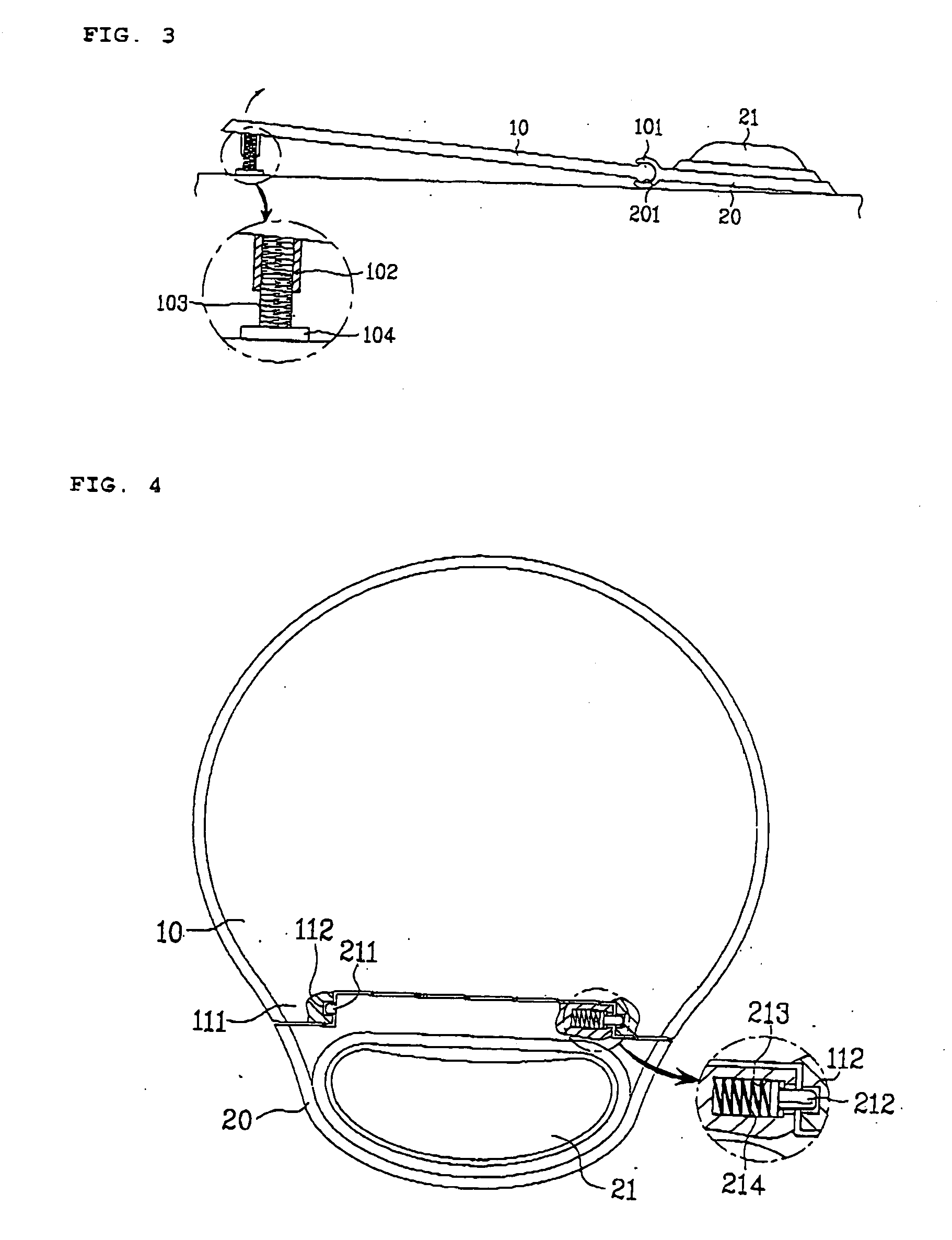
[0054]FIG. 4 illustrates a layout of a mouse pad according to a second embodiment of the present invention. A mouse pad, as shown in FIG. 4, includes a coupling boss part 111 having a coupling recess 112 formed inward in one body at each end of a front edge of a wrist support part 20 and first and second rotational pins 211 and 212 protruding outward from both ends of a rear edge of a pad part 10, respectively. The first and second rotational pins 211 and 212 are inserted into the coupling recesses 112 of the coupling boss parts 111, respectively to have the pad part 10 be assembled with the wrist support part 20 to revolve.
[0055] In this case, the second rotational pin 212 is installed to move in a lateral direction of the pad part 10. A recess 213 is formed at an edge of the pad part having the second rotational pin 212 installed thereat, the second rotational pin 212 is installed at the recess 213 to move, and a compressive spring 214 is installed inside the recess 213 to suppor...
third embodiment
[0057]FIG. 5 and FIG. 6 illustrate a mouse pad according to a third embodiment of the present invention. A mouse pad, as shown in FIG. 5 and FIG. 6, includes at least one coupling holder 221, which has a coupling groove 223 provided by a pair of support pieces 222 confronting each other, at an edge of a front end of a wrist support part 20, at least one coupling recess 121 at an edge of a rear end of a pad part 10 to correspond to a position of the corresponding coupling holder 221, and a rotational shaft part 122 traversing the coupling recess 121. The rotational shaft part 122 of the pad part 10 is inserted in the coupling groove 223 of the coupling holder 221, whereby the pad part 10 is assembled with the wrist support part 20 to enable a revolving operation.
[0058] Meanwhile, even though various means for assembling the pad and wrist support parts 10 and 20 with each other are applied to the above-described embodiments of the mouse pads, these exemplary embodiments are intended ...
PUM
 Abstract
Description
Claims
Application Information
 - R&D
- Intellectual Property
- Life Sciences
- Materials
- Tech Scout
- Unparalleled Data Quality
- Higher Quality Content
- 60% Fewer Hallucinations
Browse by: Latest US Patents, China's latest patents, Technical Efficacy Thesaurus, Application Domain, Technology Topic, Popular Technical Reports.
© 2025 PatSnap. All rights reserved.Legal|Privacy policy|Modern Slavery Act Transparency Statement|Sitemap|About US| Contact US: help@patsnap.com