Antenna construction

a technology of antennas and antennas, applied in the direction of antennas, radiating element structural forms, electrical devices, etc., can solve the problems of expensive test equipment, difficult to duplicate antennas made in this manner, and insufficient production of antennas

Inactive Publication Date: 2005-10-06
STELLA DORADUS WATERFORD
View PDF18 Cites 104 Cited by
  • Summary
  • Abstract
  • Description
  • Claims
  • Application Information

AI Technical Summary

Benefits of technology

[0012] In additional embodiments, the printed circuit board may be planar and the plane of the printed circuit board at a first interior angle with respect to an outer surface of the reflector in the vicinity of the slot. The first interior angle may be between 80 degrees and 100 degrees, and, more specifically, substantially 90 degrees.

Problems solved by technology

Because this construction involves many elements soldered together, antennas made in this manner are difficult to duplicate and to produce sufficiently accurately.
As a result, the parameters of each antenna constructed in such a manner must be checked with expensive test equipment at all stages of construction.
The resulting antenna is an expensive product.

Method used


Image

  • Antenna construction
  • Antenna construction
  • Antenna construction

Examples


Embodiment Construction

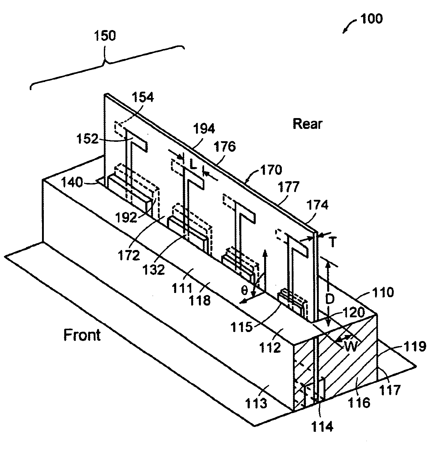
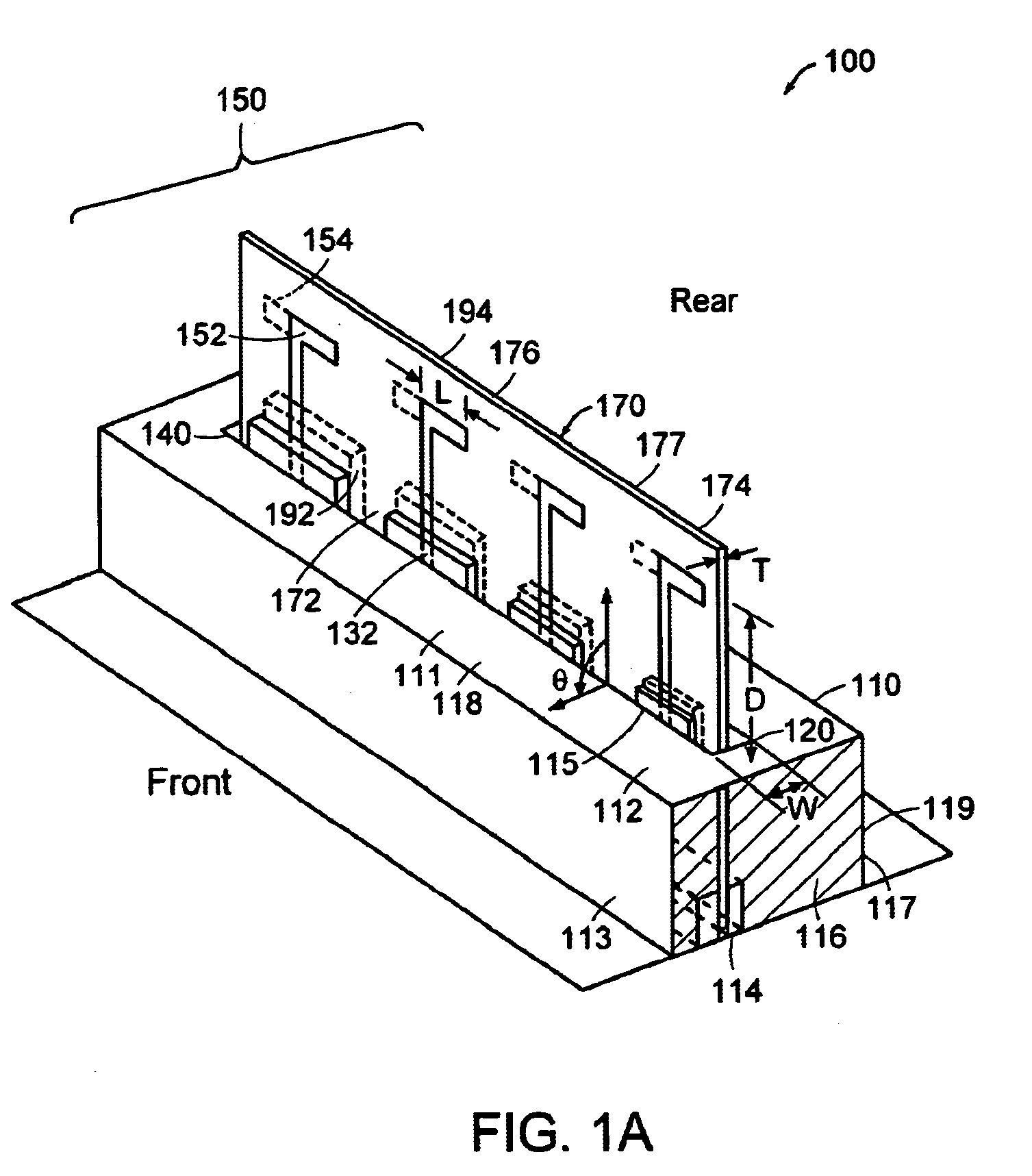
[0035] In accordance with embodiments of the present invention, an integral pattern structure and reflector are arranged to provide ease of mounting and of adjustment as well as isolation between primary radiating elements and feed harness. FIG. 1 illustrates an embodiment of the present invention in which an antenna 100 contains a printed circuit board (PCB) 170 mounted orthogonally in relation to a primary reflecting surface 112 of a reflector 110. In FIG. 1A, primary radiating elements 150 are deposits of electrically conducting material. Primary radiating elements 152 reside on the front surface 172 of an electrically insulating board 176 and primary radiating elements 154 reside on the rear surface 174 of the electrically insulating board 176. The electrically insulating property of the board 176 allows separate excitation of the primary radiating elements 152 and 154.

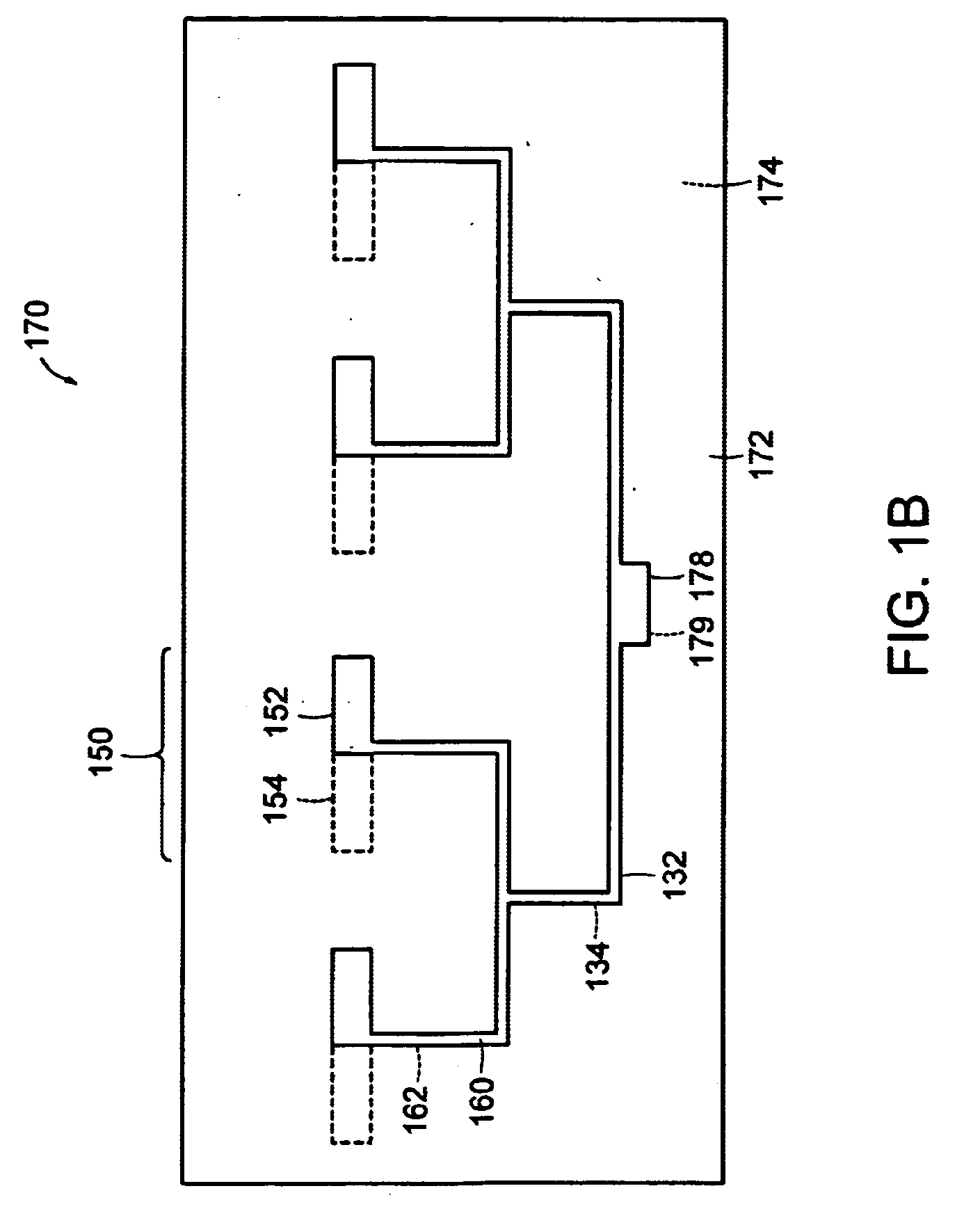
[0036] The PCB 170 is shown separately in FIG. 1B. On the front surface 172 of the PCB 170 is located a front ...


PUM


Abstract

An antenna is provided with a reflector defining a slot, a feed harness, a plurality of radiating, elements electrically connected to the feed harness through the slot, and a printed circuit board including the feed harness and the radiating elements. The periphery of the slot is laterally separated from the feed harness and from the printed circuit board. The radiating elements and the feed harness may be located on different sides of the reflector. The feed harness and the radiating elements may be formed on an integral pattern structure. The position of the feed harness relative to the positions of the radiating elements may be adjustable.

Description

CROSS REFERENCE TO RELATED APPLICATIONS [0001] The present application claims priority from Irish application serial number E 2004 / 0232, filed on Apr. 1, 2004. [0002] 1. Technical Field [0003] The present invention relates to an antenna, more particularly to a pattern antenna capable of reliable construction and operation. [0004] 2. Background Art [0005] An antenna is a passive device which focuses electromagnetic radiation to attain intended directivity or coverage. A ground plane, or reflector, is a conductive surface which acts to ground the antenna, to direct the radiation as desired, and to shield other directions from stray radiation. [0006] In an antenna where the primary radiating elements are located on a printed circuit board (PCB) and are soldered to a wire network harness, the ground plane is positioned between the primary radiating elements and the supporting network to prevent undesirable radiations from affecting the feed harness. Because this construction involves ma...

Claims


Application Information

Patent Timeline
Patent Type & Authority Applications(United States)
IPC IPC(8): H01Q9/28H01Q19/10H01Q21/08H01Q21/12
CPCH01Q9/285H01Q21/08H01Q19/108
Inventor BROWNE, EDWINATHOMPSON, NAOMIBROWNE, JAMES
Owner STELLA DORADUS WATERFORD
Why Eureka
Try Eureka