

Balance-adjustable bottom rail for window blind
- Summary
- Abstract
- Description
- Claims
- Application Information
AI Technical Summary
Benefits of technology
Problems solved by technology
Method used
Image

Examples
Embodiment Construction
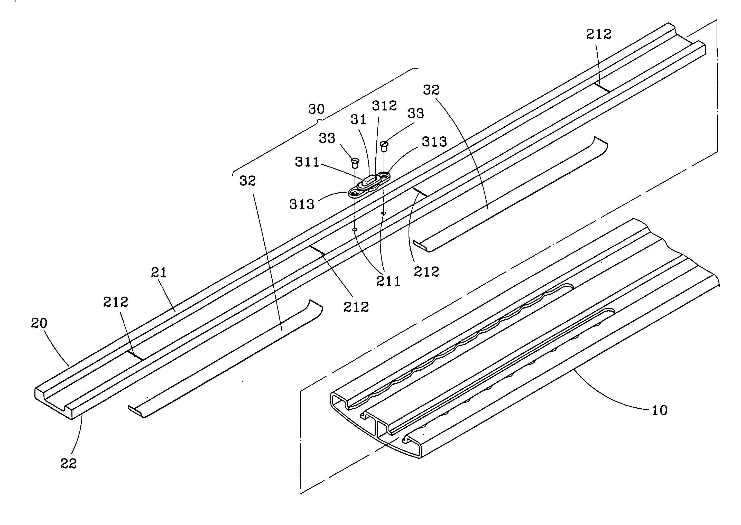
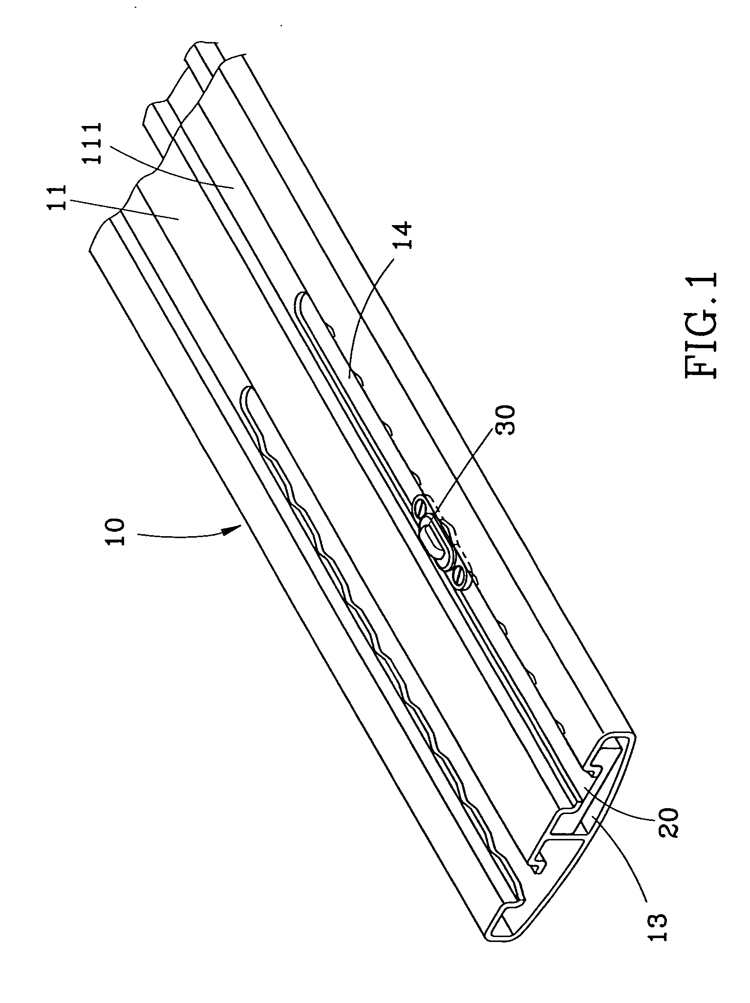
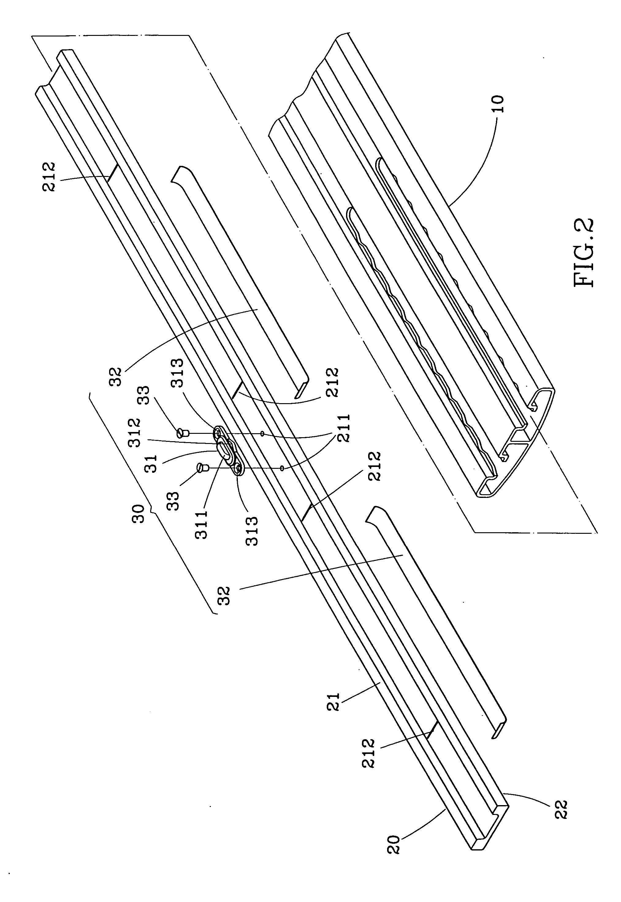
[0020] Referring to FIGS. 1-5, a balance-adjustable bottom rail for a window blind in accordance with the first preferred embodiment of the present invention is shown comprised of a rail body 10, a weight 20, and a positioning device 30.
[0021] The rail body 10 is a flat elongated hollow member having a longitudinal axis parallel to a long side thereof, a top wall 11, a bottom wall 12 transversely curved outwards, two longitudinal grooves 111 formed in the top wall 11 and extended along the longitudinal side of the rail body 10, two receiving chambers 13 defined in between the top wall 11 and the bottom wall 12, two longitudinal sliding slots 14 cut respectively through the top wall 11 in communication between the receiving chambers 13 and the longitudinal grooves 111, and a serrated engagement portion 141 arranged along one long side of each longitudinal sliding slot 14.
[0022] The weight 20 is a narrow elongated heavy member inserted into one receiving chamber 13 of the rail body ...
PUM
 Abstract
Description
Claims
Application Information