This helps you quickly interpret patents by identifying the three key elements:
Problems solved by technology
Method used
Benefits of technology
[0034]1. The powder dry-pressing molding device of the present invention has a compact structure and is provided with the scraping mechanism, the scraping mechanism is provided with the cam, the connecting piece, the middle piece and the like, the device adopts purely mechanical transmission, each part is convenient to adjust, and the near rest section of the cam is provided with the wave structure, so that the pusher can be driven to make a small range of reciprocating movement on the workbench above the middle mold, so as to scrape the powder.
[0035]2. The powder dry-pressing molding device of the present invention is provided with the first pressure mechanism and the second pressure mechanism, which can realize simultaneous or non-simultaneous pressurization on the powder in two directions, the blank density is uniform, and the molding effect is good.
[0036]3. In the powder dry-pressing molding device of the present invention, both the upper driving mechanism and the lower driving mechanism adopt a crankshaft, and the pressure is applied to the powder in many times and from light to heavy. The torque transmitted by the crankshaft is constant. During pressing, the upper slide block is driven by the upper crankshaft to move downward, the moment arm decreases slowly, and the punching force of the upper punch increases slowly. In a similar way,
Problems solved by technology
The pressure applied by the mechanical press changes with the amount of powder filling, which will easily cause difference in size shrinkage after sintering and affect the product quality.
The inventors found that the most widely used traditional dry-pressing molding equipment has the defects of complex structure and inconvenient operation.
A traditional screw press carries out molding by means of the impact kinetic energy of a flywheel system, the pressing speed is too high, and the pressure rise is uneven, so that the actual pressure of each part of the powder is uneven, resulting in poor blank density uniformity and even serious defects of cracking and larger deformation.
By full use of the characteristic of hydraulic transmission, a traditional hydraulic molding machine can obtain great pressure, easily makes a linear movement, realizes speed adjustmen
Method used
Image
Click on the blue label to locate the original text in one second.
Reading with bidirectional positioning of images and text.
Examples
embodiment 2
[0158]The present embodiment discloses a working method of the powder dry-pressing molding device described in the embodiment 1:
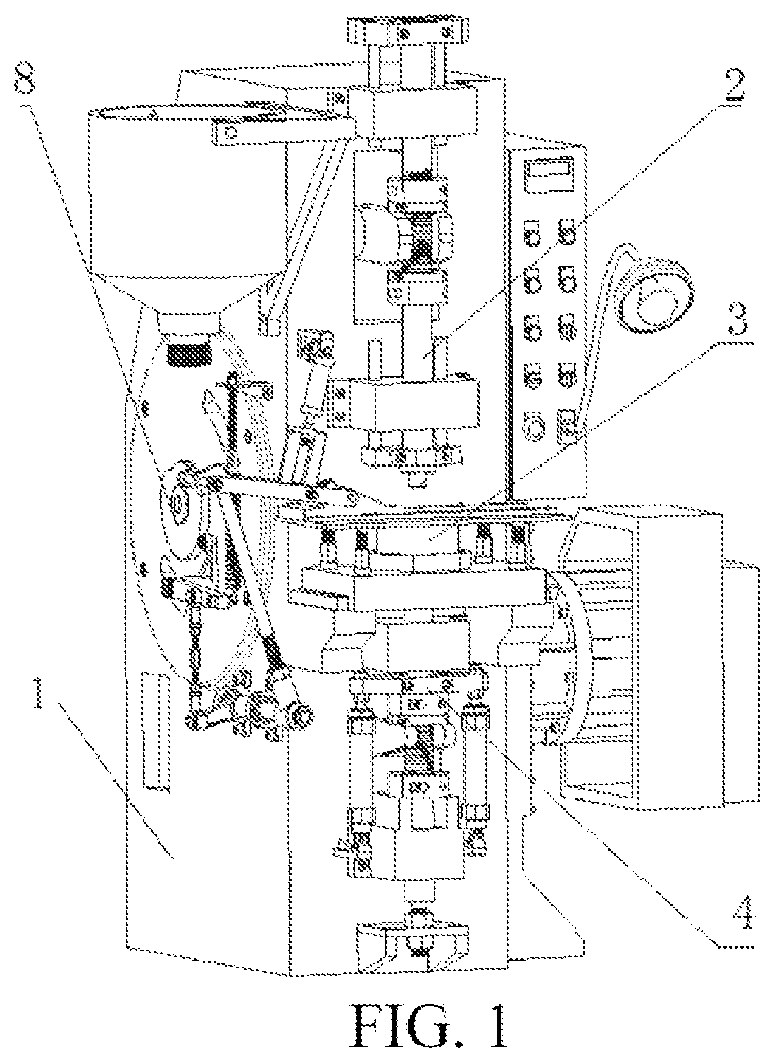
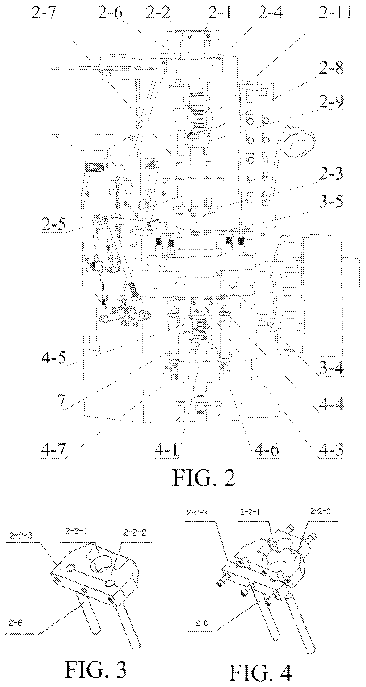
[0159]Powder is put into the barrel, and the barrel is communicated with the feeding channel of the pusher through a feeding pipe. In the initial state, the roller is in contact with the far rest section of the cam, the cam is started to rotate, and the roller begins to enter the near rest section of the cam. At this time, the feeding channel of the pusher is aligned with the compacting space formed by the mandrel and the middle mold, the resetting cylinder works to drive the lower punch to move downward, a vacuum is formed in the compacting space, the powder is sucked into the compacting space, and thus, the compacting space is filled with the powder. By adopting the method of vacuum suction of the powder, the internal void of the powder is reduced, and the molding quality is higher. The cam continues to rotate, and under the action of the wave structure, ...
PUM
Abstract
The present invention relates to a powder dry-pressing molding device and method. The powder dry-pressing molding device includes a rack, the rack is provided with an first pressure mechanism, a workbench mechanism and a second pressure mechanism in sequence along an up-and-down direction, and one side of the workbench mechanism is provided with a scraping mechanism; the first pressure mechanism includes an upper slide block capable of moving up and down, and an upper punch is disposed at a bottom of the upper slide block; the workbench mechanism includes a middle mold seat, a workbench is fixed above the middle mold seat, a middle mold is disposed inside the middle mold seat, and a mandrel runs through the inside of the middle mold; the second pressure mechanism includes a lower slide block capable of moving up and down, a lower punch is fixed at the top end of the lower slide block, and the lower punch is capable of extending into a compacting space between the mandrel and the middle mold; and the scraping mechanism includes a pusher connected with a scraping driving mechanism and capable of moving along the workbench, the pusher is provided with a feeding channel capable of being communicated with the compacting space, and the feeding channel is capable of being communicated with a barrel disposed on the rack. The dry-pressing molding device of the present invention has a high degree of automation, can scrape the powder, and has a good processing effect.
Description
BACKGROUNDTechnical Field[0001]The present invention relates to the technical field of processing and molding of alumina ceramic, and specifically relates to a powder dry-pressing molding device and method.Related Art[0002]Descriptions herein only provide background techniques related to the present invention, and do not necessarily constitute the related art.[0003]In ceramic processing, alumina is the most common material. The alumina ceramic is a ceramic material based on alumina (Al2O3) and is used in thick film integrated circuits. The alumina ceramic has better conductivity, mechanical strength and high temperature resistance. It should be noted that ultrasonic cleaning is required. The alumina ceramic is a kind of ceramics with a wide range of applications. Due to the superior performance, the alumina ceramic has become more and more widely used in the modern society to meet the needs of daily use and special performance.[0004]The alumina ceramic is divided into high-purity ty...
Claims
Application Information
Patent Timeline
Application Date:The date an application was filed.
Publication Date:The date a patent or application was officially published.
First Publication Date:The earliest publication date of a patent with the same application number.
Issue Date:Publication date of the patent grant document.
PCT Entry Date:The Entry date of PCT National Phase.
Estimated Expiry Date:The statutory expiry date of a patent right according to the Patent Law, and it is the longest term of protection that the patent right can achieve without the termination of the patent right due to other reasons(Term extension factor has been taken into account ).
Invalid Date:Actual expiry date is based on effective date or publication date of legal transaction data of invalid patent.