
Locking Wrench for Fire Hydrant

Active Publication Date: 2020-07-09
KENNEDY VALVE
View PDF0 Cites 0 Cited by
  • Summary
  • Abstract
  • Description
  • Claims
  • Application Information

AI Technical Summary

Benefits of technology

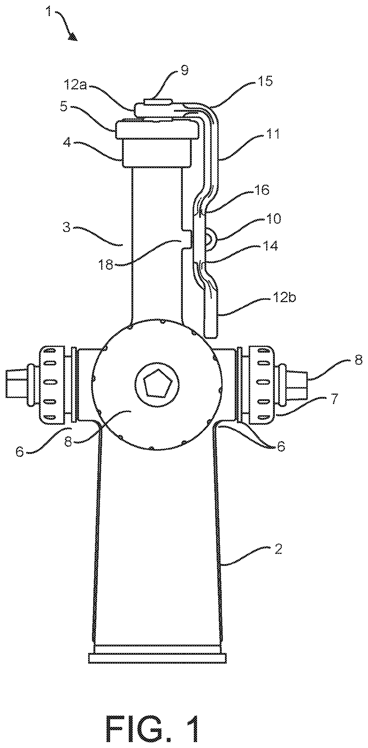
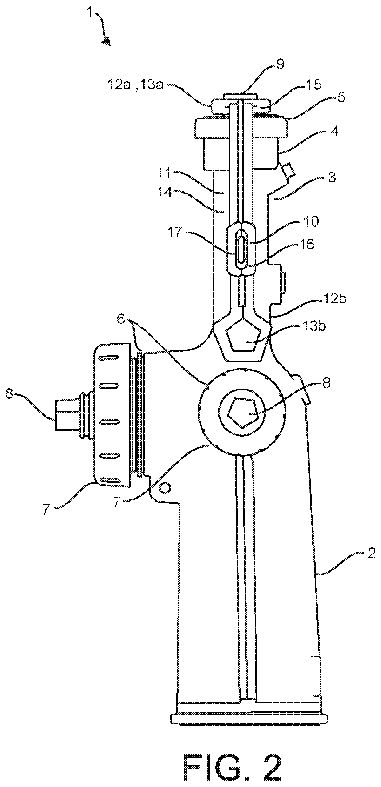
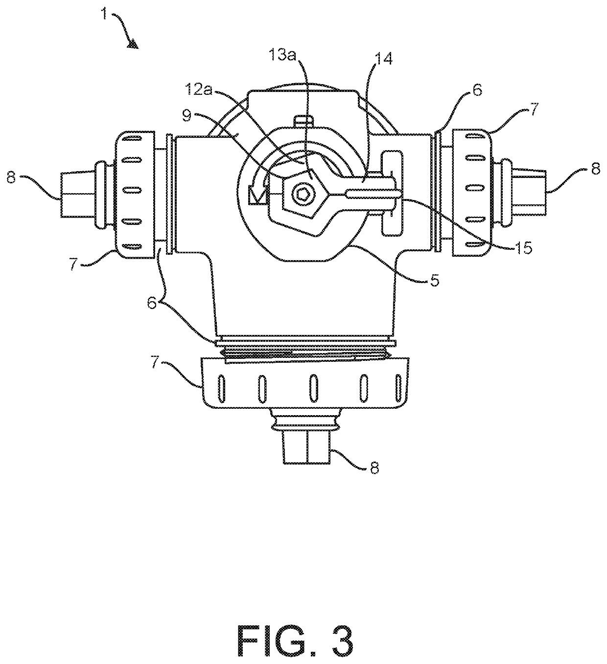
The present invention relates to a locking wrench designed to secure a fire hydrant and prevent tampering. The wrench can be two-ended, with both ends in a loop that can fit around the actuating nut of the fire hydrant. The wrench can be locked in place using an eye bolt and padlock locking arm. The shape of the wrench matches the curvature of the fire hydrant, and other fittings on the fire hydrant can be adjusted by the wrench. The top of some fire hydrants have a narrow cylindrical neck, so the wrench can conform better to the shape of the fire hydrant and be more secure. The wrench can perform the dual roles of securing the actuating nut of the fire hydrant and being configured to actuate the fire hydrant when it is removed from its locking position.

Problems solved by technology

Fire hydrant tampering incidents cause significant problems.
The negative consequences of unpermitted use of fire hydrants for non-emergency related purposes, such as summer recreation or cooling, include the waste of large amounts of treated drinking water, causing water pressure reductions that may hinder firefighting in the event of a fire, causing damage to a fire hydrant that may in turn cause firefighters to waste time and money, causing the municipal water supply to become discolored, causing expensive water damage to streets, sidewalks and private property, causing traffic and safety problems by flooding streets, and causing the possibility of injuring passersby directly by launching fire hydrant caps as projectiles or by hitting passersby with forceful water streams.
Some introduce considerable mechanical complexity to the fire hydrants.
Many of them require firefighters to have access to a special tool and render common tools such as conventional wrenches useless for actuating the hydrants.
Some make use of sensors coupled to a transmitter that may function to summon law enforcement after tampering has taken place, offering no preventive value and requiring maintenance of a power source.
One scheme would require firefighters to carry a special magnetic wrench, which would be susceptible to failure if the magnetism in the wrench were to degrade over time.

Method used


Image

  • Locking Wrench for Fire Hydrant
  • Locking Wrench for Fire Hydrant
  • Locking Wrench for Fire Hydrant

Examples


Embodiment Construction

[0031]In the following description, reference is made to the accompanying drawings that form a part thereof, and in which is shown by way of illustration specific exemplary embodiments in which the present teachings may be practiced. These embodiments are described in sufficient detail to enable those skilled in the art to practice the present teachings and it is to be understood that other embodiments may be utilized and that changes may be made without departing from the scope of the present teachings. The drawings and description are to be regarded as illustrative and non-limiting in nature. The following description is, therefore, merely exemplary. Like reference numerals designate like elements throughout the specification.

[0032]When an element or layer is referred to herein as being “on”, “engaged to”, “connected to” or “coupled to” another element or layer, it may be directly on, engaged, connected or coupled to the other element or layer, or intervening elements or layers ma...


PUM


Abstract

A wrench for securing, actuating and preventing tampering with a fire hydrant is disclosed. In useful embodiments, the wrench can be a two-ended wrench having a loop that encloses a pentagonal opening at either end of an elongated handle, where the handle can include in a nonterminal portion a slot. In a locking mode, the wrench can accept at a first end an actuating nut of the fire hydrant and can be locked in place by inserting a locking arm of a padlock through an eye bolt that is secured to a side of the fire hydrant and inserted through the slot. The wrench can be unlocked and removed, whereupon a second end can be used to turn the actuating nut as well as to remove water outlet caps and adjust nozzles.

Description

BACKGROUND OF THE INVENTIONField of the Invention[0001]The invention relates to fire hydrant security. More particularly, the invention pertains to a wrench configured to open and close a main valve of a fire hydrant and to lock the main valve of the fire hydrant from opening or closing.Description of the Related Art[0002]Fire hydrant networks are a vital tool for public safety officials, and municipalities recognize the importance of keeping them in good working order by preventing vandals from activating them. Fire hydrant tampering incidents cause significant problems. The negative consequences of unpermitted use of fire hydrants for non-emergency related purposes, such as summer recreation or cooling, include the waste of large amounts of treated drinking water, causing water pressure reductions that may hinder firefighting in the event of a fire, causing damage to a fire hydrant that may in turn cause firefighters to waste time and money, causing the municipal water supply to b...

Claims


Application Information

Patent Timeline
IPC IPC(8): F16K35/06E03B9/06E05B67/38
CPCE05B67/383E03B9/06F16K35/06E03B9/02F16K35/10F16K35/00
Inventor KENNEDY, PAUL
Owner KENNEDY VALVE
Learn More