Instrument to prepare an intra-uterine device for insertion

Pending Publication Date: 2021-02-04
PREGNA INT
View PDF4 Cites 3 Cited by
  • Summary
  • Abstract
  • Description
  • Claims
  • Application Information

AI Technical Summary

Benefits of technology

[0018]The downfolding device has a fence and an open channel, spaced by a platform, on a base. An external side of the fence has a depression on either side, a concave, and generally complementary to a convex shape of human thumb and human fingers and therefore acts as a receptacle; consequently a service provider can hold the downfolding device firmly and which facilitates easy and secure loading of IUD into the graduated tube. An internal side of the fence has a converging opening, turning into a narrow zone and ending into a well having a depth. The narrow zone has a projecting ridge on either side, leaving a clear passage. The well has an orienting step on either side. The open channel has a circular orifice having a sector of angle measure at least 220°. The circular orifice merges with a pair of divergent walls, having an exit opening that is initially marginally less than an external diameter of the graduated tube. A root thickness of the base in-between the open chan

Problems solved by technology

Loading or preparing of IUD needs to be done minutes before it is required to be inserted in uterus, and if done earlier, or if supplied duly loaded, then the IUD shall not return to the desired “T” shape in uterus, and shall not work effectively

Method used


Image

  • Instrument to prepare an intra-uterine device for insertion
  • Instrument to prepare an intra-uterine device for insertion
  • Instrument to prepare an intra-uterine device for insertion

Examples


Example

[0045]Preferred embodiment of an instrument to load and insert a downfoldable intra-uterine device and process thereof according to present invention will now be described in detail, with reference to the accompanying drawings. The terms and expressions which have been used here are merely for description and not for limitation. The term “preparing” and “loading” are used interchangeably.

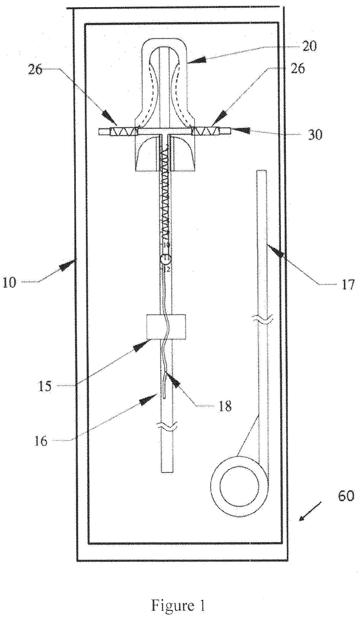
[0046]FIG. 1, the instrument 10 according to present invention comprises a downfolding device 20, a graduated tube 16, a push rod 17, a stopper 15, and an IUD 30, encased in a transparent pouch 60.

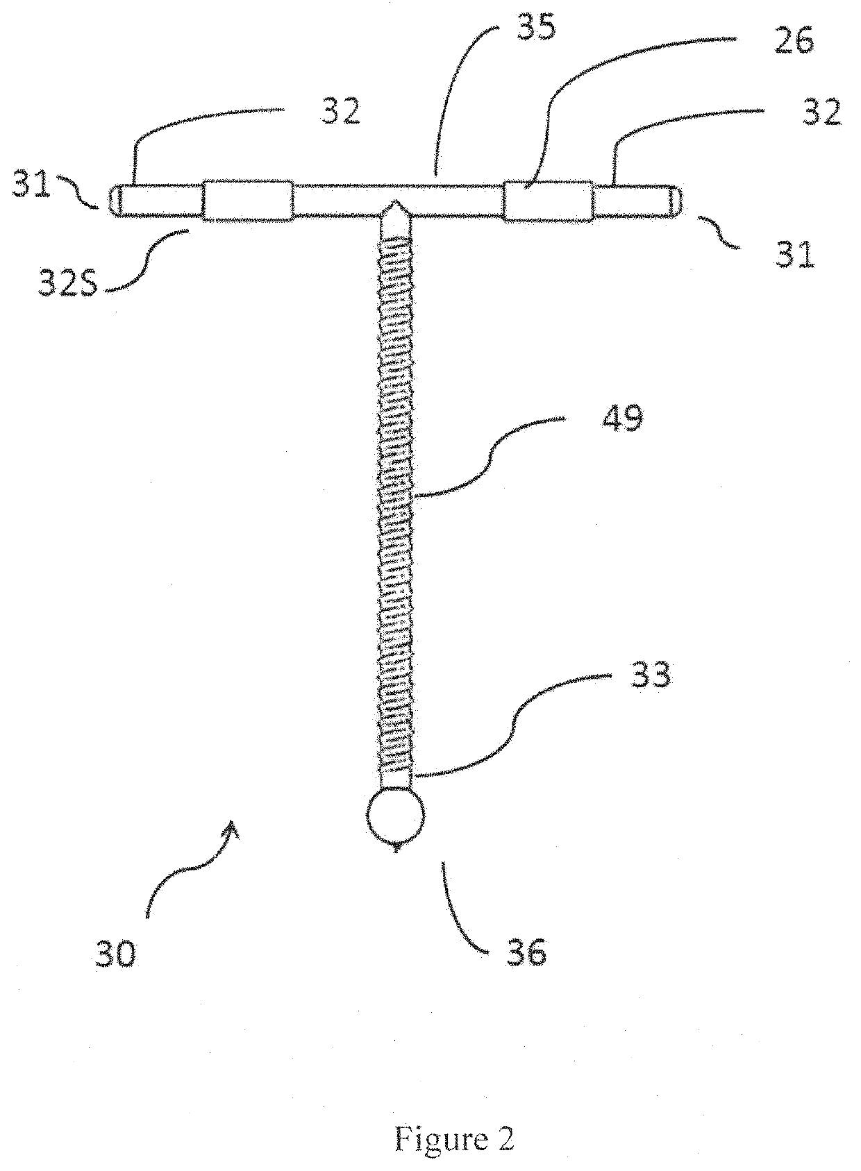
[0047]FIG. 2, the IUD 30 is essentially in a “T” shape, comprising a moulded frame 35 having a metallic envelope / wire 49 wrapped around a stem 33, preferably with a sleeve 26 on each of a pair of arms 32. The sleeve 26 is generally made of medical grade copper.

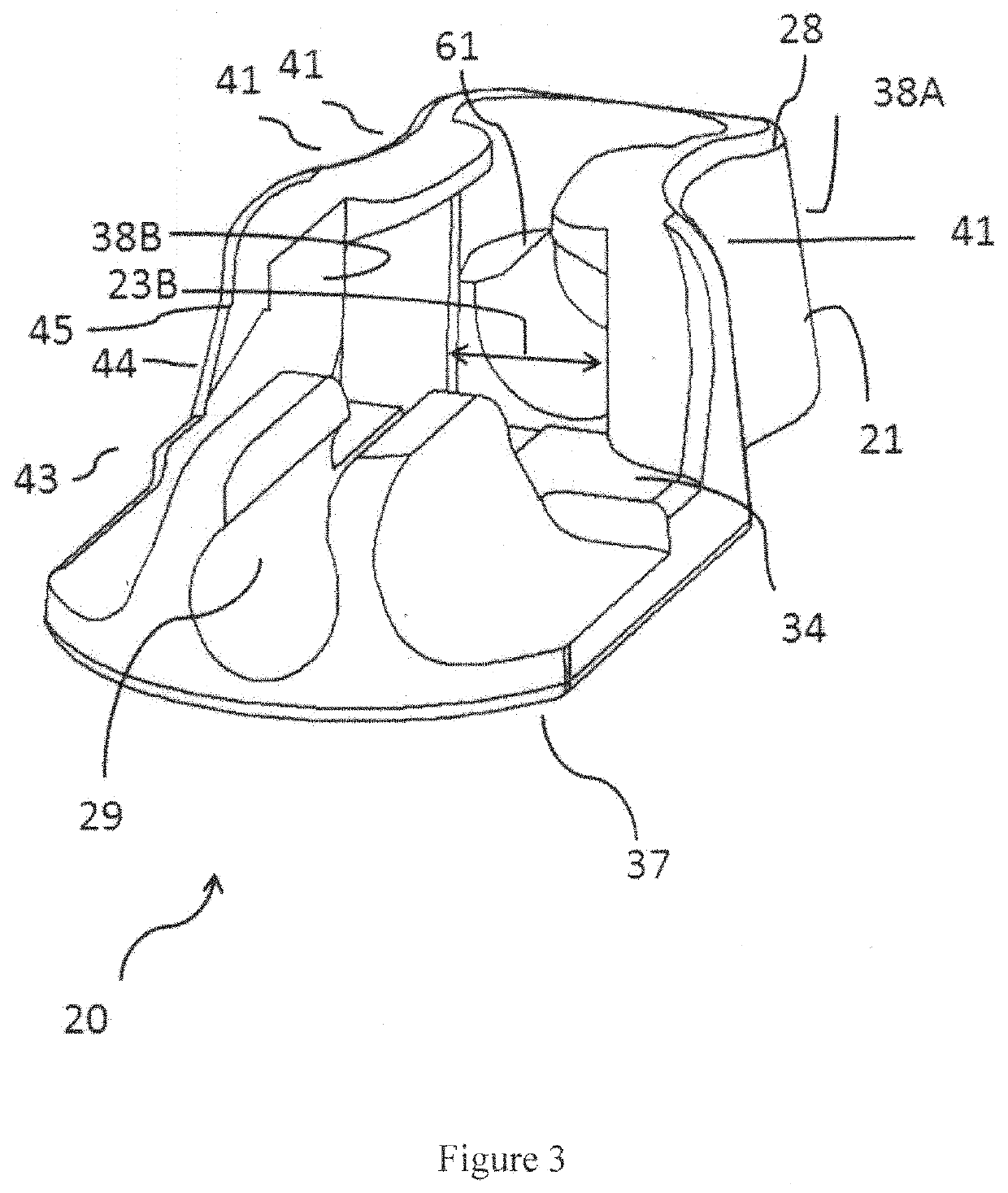
[0048]FIGS. 3, 4, 5A, the downfolding device 20 has a fence 21 and an open channel 29, spaced by a platform 34, on a base 37. An external side 38A o...


PUM


Abstract

An instrument 10 to prepare an intra-uterine device 30 for insertion in uterus 50 of woman, comprising a downfolding device 20, a graduated tube 16, a push rod 17, a stopper 15, and an IUD 30; the downfolding device 20 having a concave depression 41 on either side, an open channel 29 of a circular orifice 46 having a sector of angle measure 46A at least 220° and having an exit opening 48 initially marginally less than an external diameter 22B of the graduated tube 16, a root thickness 37B of the base 37 in-between the open channel 29 such that the exit opening 48 increases by the base 37 flexing; the graduated tube 16 has an internal diameter 22D of a far-end opening 22a of the graduated tube 16 sufficient to capture the stem 33 and both arms 32 of the IUD 30 in a downward triangular formation 51.

Description

FIELD OF THE INVENTION[0001]The present invention relates to intra-uterine device, particularly to an instrument which is to load and insert intra-uterine device and the process of loading and inserting the intra-uterine device hygienically.BACKGROUND OF THE INVENTION[0002]There are several female contraceptives available. Intra-uterine device (herein after abbreviated as IUD) is a long- or medium-term contraceptive which is placed in the uterus of female. Most commonly available IUDs are in the shape of the English letter “T” since this shape is found appropriate to the shape of uterus.[0003]While the IUDs are required to be in the shape of “T”, they cannot be inserted in this form as the opening of the cervix is small. Arms forming “T” of IUD are folded either upwards or downwards so that IUD can be contained in the opening of a narrow tube which then can be inserted in the uterus. This process of folding the IUD so that the instrument is ready to insert is known as loading or pre...

Claims


Application Information

Patent Timeline
IPC IPC(8): A61F6/18
CPCA61F6/18A61F6/144
Inventor TAPARIA, MUKUL
Owner PREGNA INT
Why Eureka
Try Eureka