Structure and method for holding and protecting vials in levels

Active Publication Date: 2005-10-20
MILWAUKEE ELECTRIC TOOL CORP
View PDF14 Cites 20 Cited by
  • Summary
  • Abstract
  • Description
  • Claims
  • Application Information

AI Technical Summary

Benefits of technology

[0025] In addition to enhancing the visibility of the vial, in certain embodiments the ring member provides impact absorption to the level by providing inner and outer layers which are elastomeric and provide impact-absorption to the level. Such inner and outer layers may have varying densities and compressibility to provide a desired impact absorption level. In certain embodiments, the

Problems solved by technology

However, such attachment often does not provide sufficient support or p

Method used


Image

  • Structure and method for holding and protecting vials in levels
  • Structure and method for holding and protecting vials in levels
  • Structure and method for holding and protecting vials in levels

Examples


Example

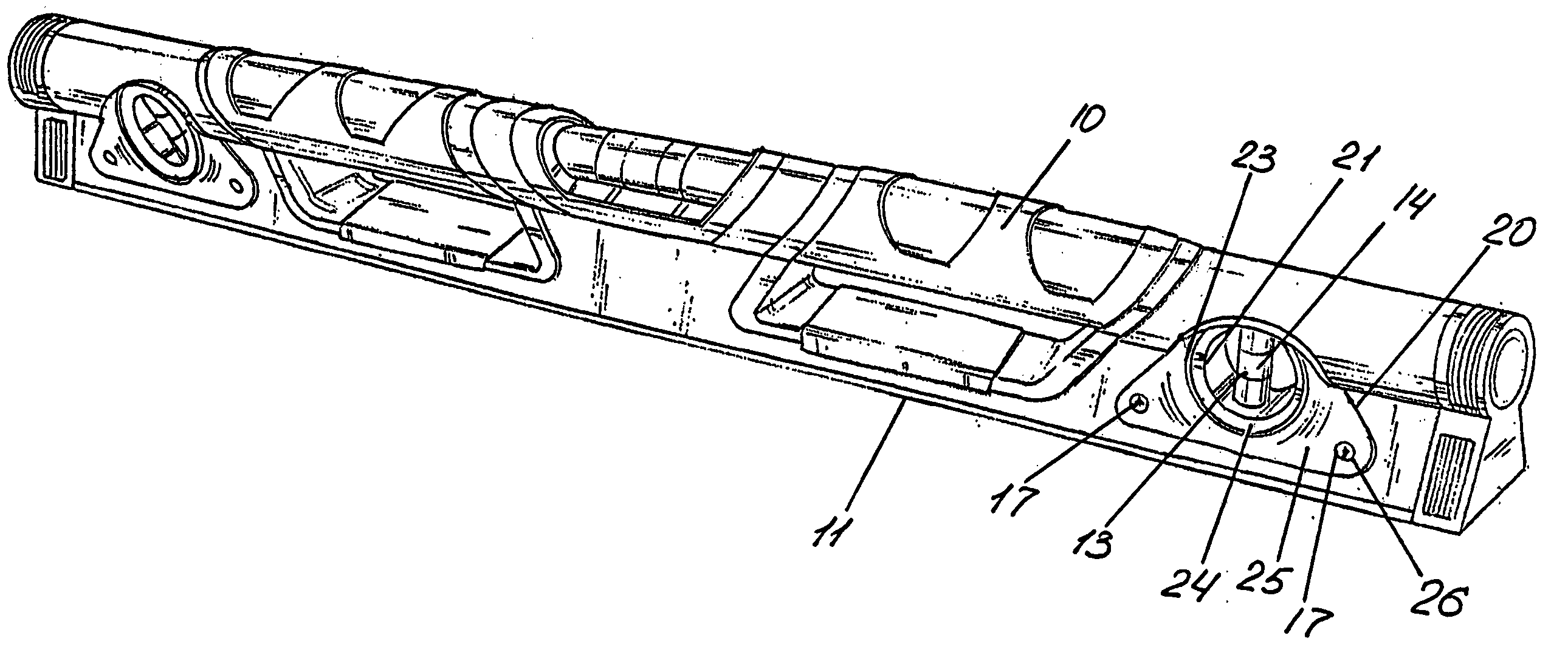
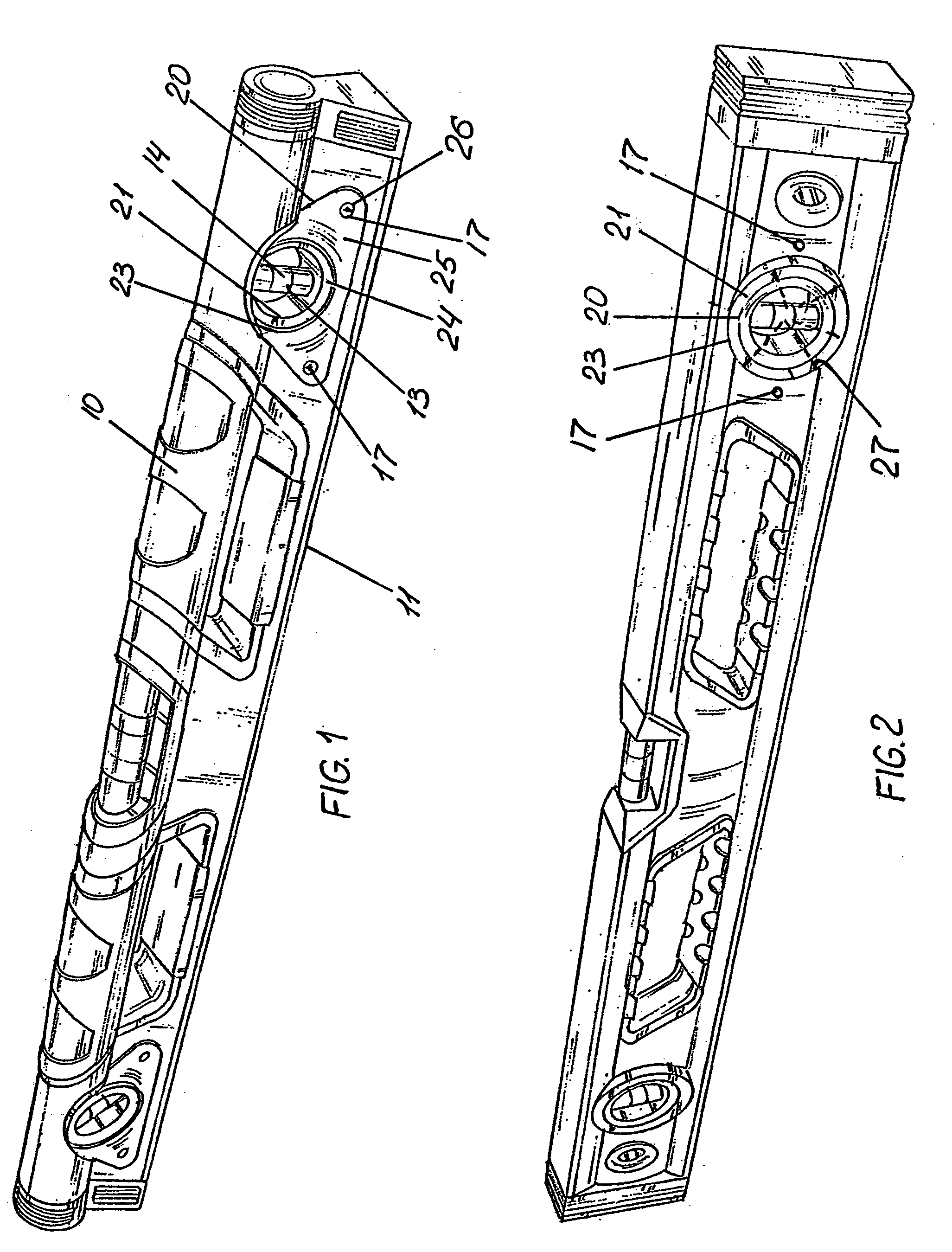
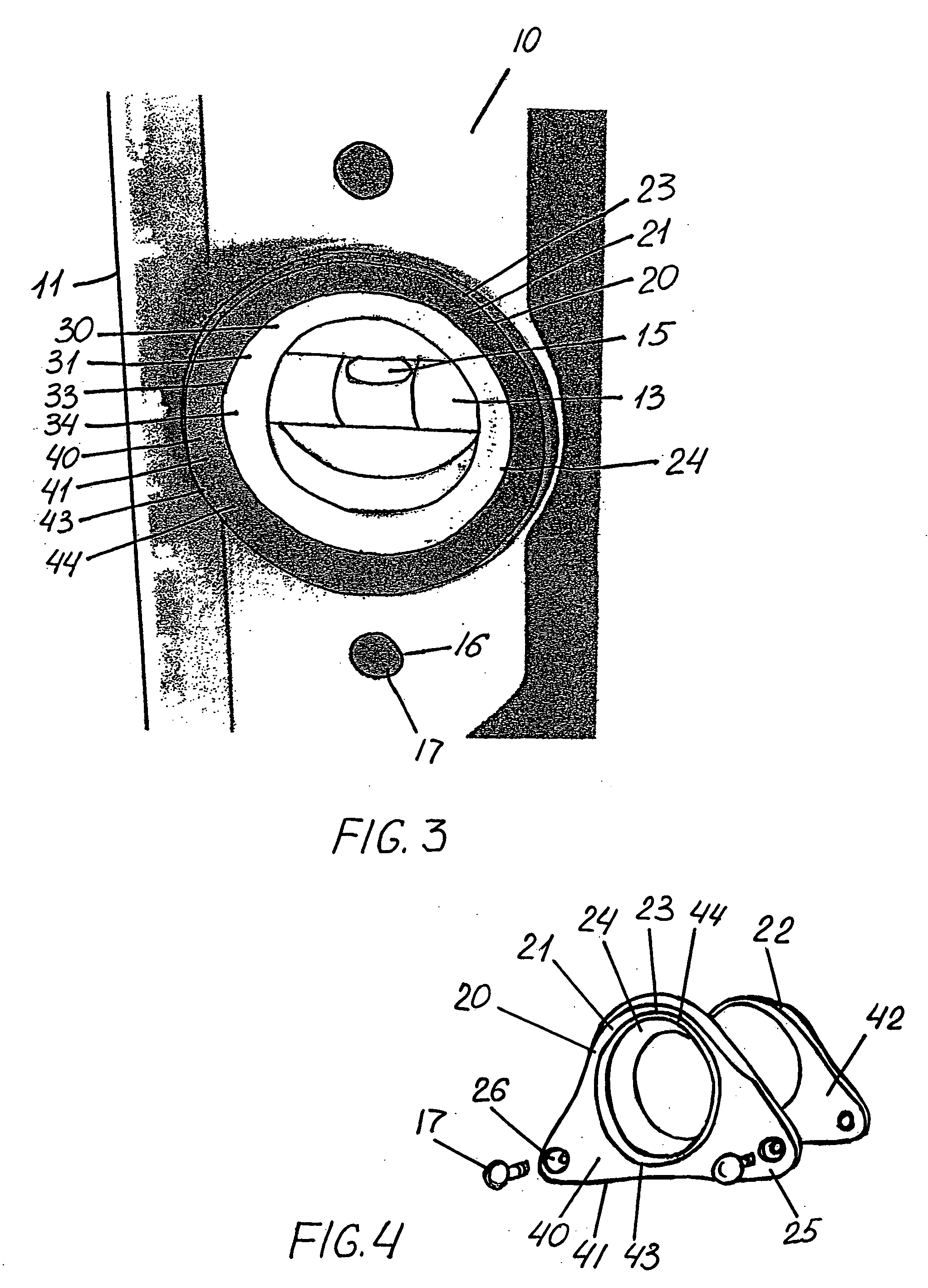
[0032]FIGS. 1 and 2 are perspective views of alternate designs of a level 10 having a ring member 20 holding a vial 13. Level 10 includes a measuring surface 11 for contacting a surface to measure or set its levelness. Level further includes a recess 12 (shown more clearly in FIG. 6) for receiving vial 13.

[0033] Vial 10 is received in recess 12 and is fastened therein and held by ring member 20. Ring member 20 includes a front portion 21 and a rear portion 22 (shown in FIGS. 4 and 5). Ring member 20 has a beveled edge 23 and includes a funnel-shaped surface 24 defining slope lines 27. As shown, slope lines 27 intersect with vial 10, and more exactly, with a central portion 14 of vial 10. Alternatively, vial 10 may be positioned between the slope lines 27 of opposite sides of the funnel-shaped surface 24.

[0034]FIG. 1 depicts a ring member 20 having wing members 25 which are external of level 10 when constructed. FIG. 2 depicts a ring member 20 having wing members 25 (shown in FIG. ...


PUM


Abstract

A level and a method of forming such a level are disclosed. The level comprises a body having a measuring surface and a recess, a vial positioned in the recess at an angular relationship to the measuring surface, and a ring member enclosing the vial within the recess, the ring member engaging the vial and the body and fastened to the body, the ring member having a beveled edge forming a funnel-shaped surface defining slope lines, the slope lines intersecting the vial, whereby the vial is protected by the level and ring member while visibility of the vial is enhanced. The method comprises providing a level with a recess and a measuring surface, positioning the vial in the recess at an angular relationship to the measuring surface, and enclosing the vial within the recess with a ring member, the ring member having beveled edges forming a funnel-shaped surface.

Description

FIELD OF THE INVENTION [0001] This invention relates to geometric instruments and, more particularly, to levels (sometimes referred to as “spirit levels” used by carpenters and the like. BACKGROUND OF THE INVENTION [0002] Levels are used by carpenters, masons, drywallers and the like for helping to assure that surfaces are horizontal, vertical, or at a specified angular relationship to the horizon. A typical level includes at least two vials, one each for ascertaining whether a surface is “level,” i.e., horizontal, or “plumb,” i.e., vertical. [0003] A level vial comprises a tube made of clear glass or, preferably, clear plastic (acrylic, for example), the barrel-shaped cavity of which is partially filled with a liquid such as mineral spirits. The vial is not completely filled and a bubble is thereby formed when the vial is closed. Typically, two marker rings are applied to the outside of the vial in positions to visually divide the cavity into three portions of about equal length. L...

Claims


Application Information

Patent Timeline
IPC IPC(8): B43L7/00B43L9/00G01C9/28
CPCG01C9/28B43L7/00G01C9/26G01C9/32
Inventor KIM, CHARLES D.
Owner MILWAUKEE ELECTRIC TOOL CORP
Why Eureka
Try Eureka